


Verification and Performance Tests - 2
19
CC Load and Line Regulation
These tests (CC Load Effect and CC Source Effect given below) are tests of the dc regulation of the power supply's
output current. To insure that the values read are not the instantaneous measurement of the ac peaks of the output
current ripple, several dc measurements should be made and the average of these readings calculated. An example of
how to do this is given below using an Agilent 3458A System Voltmeter programmed from the front panel. Set up
the voltmeter and execute the "Average Reading" program follows:
a. Program 10 power line cycles per sample by pressing NPLC 1 0 ENTER .
b. Program 100 samples per trigger by pressing (N Rdgs/Trig) 1 0 0 ENTER .
c. Set up voltmeter to take measurements in the statistical mode as follows:
Press Shift key, f0, Shift key, N
Press ^ (up arrow) until MATH function is selected, then press >.
Press ^ (up arrow until STAT function is selected then press (ENTER).
d. Set up voltmeter to read the average of the measurements as follows:
Press Shift key, f1, Shift key, N.
Press down arrow until RMATH function is selected, then press >.
Press ^ (up arrow) until MEAN function is selected, then press ENTER.
e. Execute the program by pressing f0, ENTER, TRIG, ENTER
f. Wait for 100 readings and then read the average measurement by pressing f1, ENTER.
To repeat the measurement, perform steps (e) and (f).
CC Load Effect
This test measures the change in output current for a change in load from full scale output voltage to short circuit.
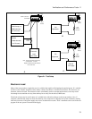
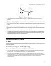
a. Turn off the supply and connect the output as shown in Figure 2-1a with the DVM connected across the current
monitoring resistor.
b. Turn on the supply and if it was set to low range readback in the previous test, set it back to high or auto.
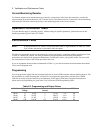
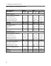
Program the current to full scale and the output voltage to the maximum programmable voltage value (Vmax) in
Table 2-2.
c. Adjust the load in the CV mode for the UUT full scale voltage in Table 2-2 as indicated on the front panel
display. Check that the CC annunciator is on. If it is not, adjust the load so that the output voltage drops slightly.
d. Record the output current reading (DVM reading/current monitor resistance value in ohms). You may want to
use the average reading program described under “CC Load and Line Regulation”.
e. Short the load switch and record the output current reading. The difference in the current readings in steps (d)
and (e) is the load effect and should not exceed the limit specified in the performance test record card for the
appropriate model under CC Load Effect.