


Troubleshooting - 3
39
Disassembly Procedures
The following paragraphs provide instructions on how to disassemble various components of the dc power
supply. Once disassembled, the components can be reassembled by performing the disassembly
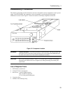
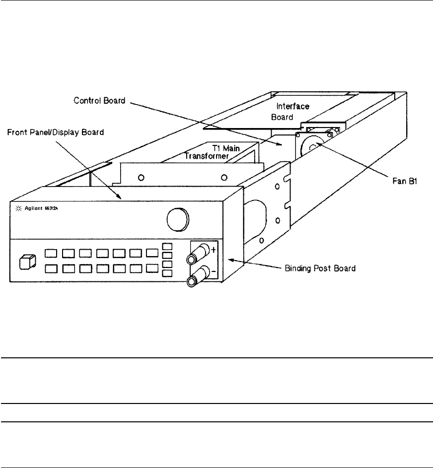
instructions in reverse order. Figure 3-2 shows the location of the major components of the unit.
Figure 3-2. Component Location
WARNING: SHOCK HAZARD. To avoid the possibility of personal injury, turn off AC power and
disconnect the line cord before removing the top cover. Disconnect the GPIB cable and
any loads, and remote sense leads before attempting disassembly.
CAUTION: Most of the attaching hardware is metric. Use of other types of fasteners will damage
threaded inserts. Refer to the list of required tools when performing disassembly and
replacement.
List of Required Tools
a. 2PT Pozidriv screwdrivers.
b. T10 and T15 Torx screwdrivers.
c. Hex drivers: 7 mm for GPIB connector,
3/16" for RS-232 connector,
1/4" for front panel binding posts
d. Long nose pliers.
e. Antistatic wrist discharge strap.