


2 - Verification and Performance Tests
18
c. Divide the voltage drop (DVM reading) across the current monitoring resistor by its resistance to convert to
amps and record this value (Iout). Also, record the current reading on the front panel display. The readings
should be within the limits specified in the performance test record card for the appropriate model under Current
Programming and Readback @ 0 Amps.
d. Program the output current to the full-scale value in Table 2-2.
e. Divide the voltage drop (DVM reading) across the current monitoring resistor by its resistance to convert to
amps and record this value (Iout). Also, record the current reading that appears on the front panel display. The
readings should be within the limits specified in the performance test record card for the appropriate model
under Current Programming and Readback @ Full Scale.
Current Sink (-CC) Operation
This test verifies current sink operation and readback.
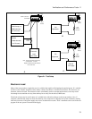
a. Turn off the supply and connect the output as shown in Figure 2-1a, except connect a dc power supply in place
of the electronic load as indicated. Set the DMM to operate in voltage mode.
b. Set the external power supply to 5 V and the current to the full scale current rating of the supply under test as in
Table 2-2.
c. Turn on the supply under test and program the output voltage to zero and the current to full scale as in Table 2-
2. The current on the UUT display should be negative and approximately 60% of the current rating.
d. Divide the voltage drop across the current monitoring resistor by its resistance to obtain the current sink value in
amps and subtract this from the current reading on the display. The difference between the readings should be
within the limits specified in the performance test record card under Current Sink Readback.
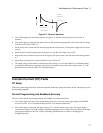
Low Range Current Readback Accuracy
This test verifies the readback accuracy of the 20 milliampere current range.
a. Turn off the supply and connect the output as shown in Figure 2-1b. Set the DMM to operate in current mode.
b. Turn on the supply under test and set the current range readback to Low or Auto. Program the output voltage to
zero and the current to the full scale value in Table 2-2. The current on the UUT display should be
approximately 0 mA.
c. Record the current reading on the DMM and the reading on the front panel display. The difference between the
two readings should be within the limits specified in the performance test record card under 20mA Range
Current Readback Accuracy @ 0A.
d. Program the output voltage to 8V and record the current reading on the DMM and the reading on the front
panel display. If the meter indicates overrange, lower the 8 volts slightly. The difference between the readings
should be within the limits specified in the performance test record card for the appropriate model under 20mA
Range Current Readback Accuracy @ +20mA
e. Turn off the supply and connect the output and an external supply as shown in Figure 2-1c. Set the DMM to
operate in current mode.
f. Turn on the external supply and program it to 8V and 1 amp. Then program the supply under test to zero volts
and 1 amp. If the meter indicates overrange, lower the voltage of the external supply slightly. The UUT display
should read approximately −20 mA.
g. Record the current reading on the DMM and the reading on the front panel display. The difference between the
two readings should be within the limits specified in the performance test record card under 20mA Range
Current Readback Accuracy @ −20 mA.