


Verification and Performance Tests - 2
17
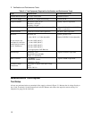
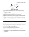
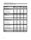
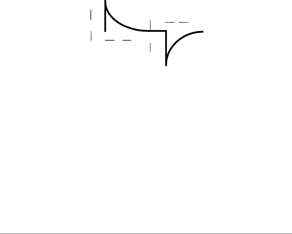
tttt
t
v
Loading
Transient
Unloading
Transient
v
t
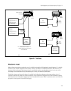
Figure 2-2. Transient Waveform
a. Turn off the supply and connect the output as in Figure 2-1a with the oscilloscope across the +S and -S
terminals.
b. Turn on the supply and program the output current to the maximum programmable value (Imax) and the voltage
to the full-scale value in Table 2-2.
c. Set the load to the Constant Current mode and program the load current to 1/2 the power supply full-scale rated
current.
d. Set the electronic load's transient generator frequency to 100 Hz and its duty cycle to 50%.
e. Program the load's transient current level to the supply's full-scale current value and turn the transient generator
on.
f. Adjust the oscilloscope for a waveform similar to that in Figure 2-2.
g. The output voltage should return to within the specified voltage (v) in less than 100uS (t). Check both loading
and unloading transients by triggering on the positive and negative slope. Record the voltage at time “t” in the
performance test record card under CV Transient Response.
Constant Current (CC) Tests
CC Setup
Follow the general setup instructions in the Measurement Techniques paragraph and the specific instructions given in
the following paragraphs.
Current Programming and Readback Accuracy
This test verifies that the current programming and readback are within specification.
a. Turn off the supply and connect the current monitoring resistor across the power supply output and the DVM
across the resistor. See "Current Monitoring Resistor" for connection information.
b. Turn on the supply and program the output voltage to 5 V and the current to zero amps. The power supply’s
current detector must be set to DC and the programming language mode to SCPI. See the specifications for high
range current readback in the User’s Guide if operating with the detector in ACDC or the language in
Compatibility mode.