


3 - Troubleshooting
40
Cover, Removal and Replacement
a. Using a T15 Torx screwdriver, unscrew the two captive screws which hold the rear bezel to the dc
power supply, and then remove the two screws from the bottom of the case.
b. Slide the cover backward until it clears the rear of the power supply.
A2 Interface Board, Removal and Replacement
To remove the Interface Board, proceed as follows:
a. Remove the cover of the power supply as described under, "Cover Removal and Replacement."
b. Remove the two 7 mm and two 3/16 inch hex screws that hold the GPIB and RS-232 connectors in
place.
c. Slide the board forward and lift the right side of the board and slide it out.
d. Unplug the 3 conductor cable from J206. Depress the release button located at the end of the connector
where the wires enter the housing.
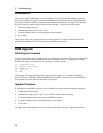
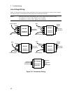
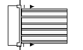
e. Unplug the flat cables. Note the position of the conductive side for reinstallation. Connectors release
the cable by pulling out end tabs as shown by the arrows in the following figure.
f. To reinstall the Interface board, perform the above steps in reverse order.
Front Panel Assembly, Removal and Replacement
This procedure removes the front panel assembly from the dc power supply.
a. Remove the Power Supply Cover as described earlier in, "Top Cover Removal and Replacement."
b. Disconnect the cable between the Front Panel board and the Interface board at the Interface board. You
may have to remove the Interface board as described above to accomplish this.
c. Using a Torx T10 driver remove the screw from the right side of the supply that holds the front panel
bracket to the chassis.
d Unplug the Binding Post cable.
e. Locate and carefully peel off the left vinyl trim to gain access to the side screw that secures the front
panel to the chassis. Using a Torx T15 driver remove the screw located behind the vinyl trim.
f. Place the power switch in the on position and slide the switch extension forward as far as it can go and
lift up to disengage from switch. Remove extension from the unit.
g. Rotate front panel forward from right side to disengage left mounting studs and pull forward.
h. To remove the right bracket, depress the plastic tab located behind the front panel in the upper right
corner.
i. To reinstall the Front Panel Assembly, perform the above steps in reverse order.