


Troubleshooting - 3
35
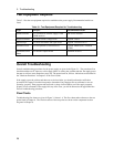
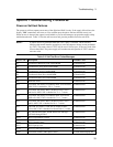
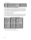
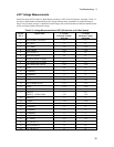
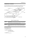
J307 Voltage Measurements
Cable W9 connects J307 of the A1 Main Board Assembly to J207 of the A2 Interface Assembly. Table 3-4
provides a quick method of determining if the voltages between these assemblies are within the normal
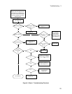
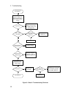
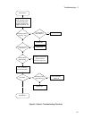
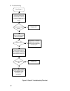
range. If any of these voltages is outside the normal range, refer to the flowcharts to further troubleshoot the
circuit associated with the abnormal voltage.
Table 3-4. Voltage Measurements at J207 (A2 Interface to A1 Main board)
A1J207
Pin #
Signal Name CV Mode
Full Scale Voltage
No Load
CC Mode
Full Scale Voltage
Full Load
1 PM_INHIBIT (Enabled) 0 0
2 OV_SCR* +5 +5
3 OV_PROG +3.9 +3.9
4 FAN_PROG +2.8 +3.8
5 OV_DETECT* +5 +5
6 SW_POS (Norm) +5 +5
7 RANGE_SELECT (High) 0 0
8 OS_TRIM_NEG (COMP) +1.7 +1.7
OS_TRIM_NEG (SCPI) +4.0 +4.0
9+5Vs +5 +5
10 COMMON 0 0
11 COMMON 0 0
12 +15Vs +15 +15
13 -15Vs -15 -15
14 HS_THERM (@25C) +2.5 +2.5
15 FUSE +2.4 +2.6
16 IMON_H 0 +3.5
17 IMON_L
IMON_L (@20mA Out)
0
+4.8
+14.7
+4.8
18 IMON_P 0 0
19 VMON +4.8 +4.8
20 COMMON 0 0
21 COMMON 0 0
22 COMMON 0 0
23 COMMON 0 0
24 CV_PROG -4.8 -4.8
25 CC_PROG -4.8 -4.8
26 CC_DETECT* +5 0
27 CCN_DETECT* +5 +5
28 CV_DETECT* 0 +5