


1-5
6. Refer to the Cabinet Wiring Diagram (Chapter 5). Check to see that cable connectors are correctly
secured. Don’t force connectors. They’re keyed to fit in only one location. Bent pins and reversed
connections may damage your game and void the warranty.
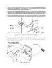
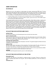
7. You can install an extra padlock to secure the rear door. You’ll find a hasp in the spare parts bag.
Remove the two lock bracket nuts from inside the cabinet, above the rear door opening. Slide the
hasp onto the bolts so that it protrudes from the hole in back of the cabinet. Reinstall nuts and tighten.
8. Modify the lock plate at the top of the rear door. Remove the bolts and nuts from the lock plate.
Rotate the plate so that the slot will be above the door. Reinstall the bolts and nuts and tighten firmly.
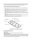
INSTALL THE DOOR LOCK AND SECURITY BRACKETS
9. The power cord is with the spare parts. Remove and save four screws from the line cord cover plate
at the rear of the cabinet. Match the holes on the IEC plug with the prongs in the receptacle. Push the
plug firmly to seat it. Route the cord away from cabinet wheels and foot traffic areas. Hang excess
cord on the plastic clip near the vent.