


7-9
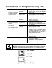
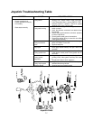
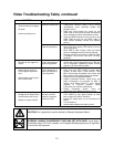
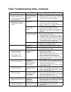
Video Troubleshooting Table,
continued
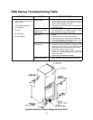
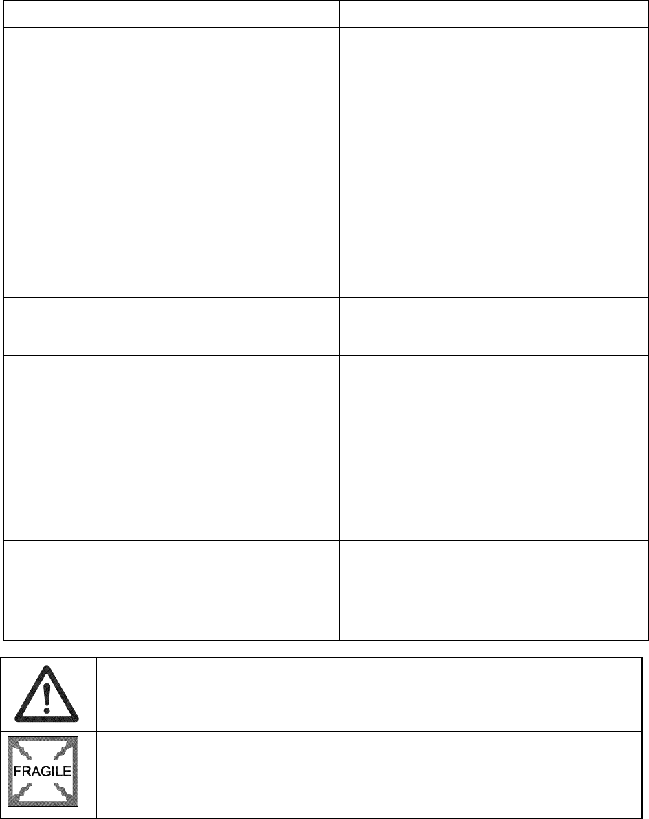
SYMPTOM CAUSE REQUIRED ACTION
Improper components
1. Verify that hard disk drive is correct for this VGM
(video game machine). Label on drive records
manufacturer name, assembly number and
program version.
2. Verify that circuit boards are correct for this
VGM. Label on each board records manufacturer
name, assembly number and hardware version.
3. Verify that ROM instruction set is correct for this
VGM. VGM set only has one ROM. Label on
ROM records assembly number and software
version.
•
Game screens don’t appear
•
No audio
•
Power-up self-test runs
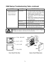
Hard drive problems
1. Turn VGM on. Immediately look under hard
drive. Hard Drive Activity LED flashes if drive is
operating properly.
2. Allow VGM to load normally. Note and record
any error messages that occur during self-test.
3. Remove hard drive and install it in working VGM.
If symptom recurs there, hard drive is faulty.
Replace it.
•
Blotches of color appear on
screen
Picture tube aperture
mask is magnetized
Remove diskettes from room. Demagnetize
monitor with external degaussing coil. Take care
not to magnetize neighboring VGMs. Monitor
may be on or off for this procedure.
•
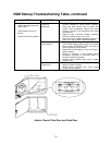
White areas in center of
screen appear tinged with
color
•
Object edges have fringe of
one or more colors
Picture tube purity or
static convergence is
out of alignment
1. Turn on VGM (video game machine).
2. Press and hold TEST MODE to enter Menu
System. At Main Menu, select Monitor Tests
Menu. Run through Crosshatch, Red, Green and
Blue screens to find clearest display of problem.
3. Display screen with greatest problem.
4. Display Crosshatch Screen. Locate purity and
static convergence ring magnets on back of
monitor neck. Watch screen in mirror. Adjust
magnets to minimize problem. Follow
instructions from monitor manufacturer.
5. Display Crosshatch Screen. Touch up
adjustments while watching screen in mirror.
•
Background of Attract Mode
screens seems out of sync
•
Words on screen read OK
Someone set DIP
switch for resolution
lower than VGA
1. VGM only outputs VGA video. Press and hold
TEST MODE to enter Menu System. At Main
Menu, select DIP Switch Test Menu.
2. Locate DIP switch bank U12 on the Sound I/O
Board.
3. Turn off switch 2.
4. Reenter Attract Mode and check screens.
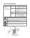
CAUTION:
Don’t operate the monitor without its Remote Adjustment Board.
WARNING: HANDLE FLUORESCENT TUBE AND CRT WITH CARE.
If you drop a
fluorescent tube or CRT and it breaks, it will implode! Shattered glass can fly eight feet
or more from the implosion.