


6-10
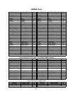
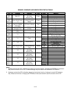
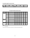
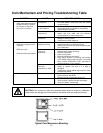
SOUND I/O BOARD LED INDICATOR STATUS TABLE
LED Location Function Color State Meaning
Off --
On --
LED1
(Note 1)
Near U11 Not Used
(Remains Off)
Green
Blinking --
Off Not in Use (No Game Linking)
LED2
(Note 2)
Near U34 & Crystal
Y1
Linking Connector
Status
Green
On Link Continuity Good
Off* No Power
LED3
(Note 2)
Near the JAMMA
Connector
-5V Power Indicator Red
On* Normal Operation
Off No PowerLED4
(Note 2)
Near U35 &
Connector P14
+12V Power
Indicator
Red
On Normal Operation
Off No PowerLED5
(Note 2)
Near Connector
P23
+5V Power Indicator Red
On Normal Operation
Off Not in Use
LED6
(Note 2)
Near U34 & Crystal
Y1
CPU Linking Activity Red
On CPU Communicating with
Ethernet Controller
Off Not in Use (No Game Linking)
On Sending Data
LED7
(Note 2)
Near U34 & Crystal
Y1
Linking Transmitting
Data
Red
Blinking Normal Operation
Off No Sound Boot ROM
On Locked Up
LED8
(Note 1)
Near U14 & Crystal
Y1
Audio Activity Yellow
Blinking Normal Operation
Off Not in Use (No Game Linking)LED9
(Note 2)
Near U34 & Crystal
Y1
Linking Receiving
Data
Yellow
On Receiving Data
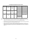
Off --
On --
LED10
(Note 1)
Near U44 & Crystal
Y2 Not Used
(Remains On)
Green
Blinking --
Off --
On --
LED11
(Note 1)
Near U44 & Crystal
Y2 Not Used
(Remains On)
Red
Blinking --
Off --
On --
LED12
(Note 1)
Near U44 & Crystal
Y2 Not Used
(Remains On)
Yellow
Blinking --
Off --
On --
LED13
(Note 1)
Near U44 & Crystal
Y2 Not Used
(Remains On)
Yellow
Blinking --
Notes
1. Software controls this LED. Indications are game and revision-specific. Changing the EPROMs on this board
may alter the function of this LED. Firmware damage may also cause new of different LED behavior.
2. Hardware controls
this LED. Indications depend on hard-wired circuitry. A change in normal LED behavior
may indicate a circuit fault. Changing the EPROMs on this board shouldn’t alter the function of this LED.