


6-9
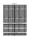
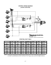
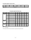
SOUND I/O BOARD JUMPER POSITION TABLE *
Jumper Location Function Meaning Position State
Input Mode Pins 1 & 2
J1
(Note 1)
Near U9 & Crystal Y3 I/O Connector P2
Output Mode Pins 2 & 3
Positive Sync Jumper Not
Installed
J2 Between U35 & U10 Video Sync
Negative Sync Pins 1 & 2
Input Mode Pins 1 & 2
J3
(Note 2)
Near U15 I/O Connector P4
Output Mode Pins 2 & 3
J4 None None Not Used None
---
Input Mode Pins 1 & 2
J5
(Note 2)
Between U15 &
Connector P2
I/O Connector P4
Output Mode Pins 2 & 3
J6 None None Not Used None
---
J7 None None Not Used None
---
Input Mode Pins 1 & 2
J8
(Note 1)
Between U9 &
Connector P4
I/O Connector P2
Output Mode Pins 2 & 3
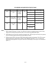
Notes
1. Configure I/O port P2 by setting both jumpers J1 and J8 to input or output mode.
2. Configure I/O port P4 by setting both jumpers J3 and J5 to input or output mode.