


6-2
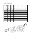
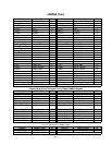
JAMMA Chart
Function Wire Color Pin Function Wire Color Pin
Ground Black A Ground Black 1
Ground Black B Ground Black 2
+5VDC Red C +5VDC Red 3
+5VDC Red D +5VDC Red 4
-5VDC Yellow E -5VDC Yellow 5
+12VDC Orange F +12VDC Orange 6
Key N/C H Key N/C 7
Coin Counter 2 Brown-Red J Coin Counter 1 Brown 8
Not Used N/C K Not Used N/C 9
Speaker -, Left Brown-Gray L Speaker +, Left Red-Gray 10
Speaker -, Right Brown-White M Speaker +, Right Red-White 11
Video Green Yellow-Green N Video Red Yellow-Red 12
Video Sync Yellow-White P Video Blue Yellow-Blue 13
Service Credits White-Gray R Video Ground Yellow-Black 14
Slam Tilt Black-Green S Test Black-Blue 15
Coin 2 Black-Red T Coin 1 Black-Brown 16
2 Start Violet-White U 1 Start White 17
2 Up Violet-Black V 1 Up White-Black 18
2 Down Violet-Brown W 1 Down White-Brown 19
2 Left Violet-Red X 1 Left White-Red 20
2 Right Violet-Orange Y 1 Right White-Orange 21
2 Jump Violet-Yellow Z 1 Jump White-Yellow 22
2 Pass Violet-Green a 1 Pass White-Green 23
2 Turbo Violet-Blue b 1 Turbo White-Blue 24
Not Used Violet c Not Used White-Violet 25
Not Used N/C d Not Used N/C 26
Ground Black e -5V Ground Yellow-Brown 27
Ground Black f Ground Black 28
Solder Side of Circuit Board Component Side of Circuit Board
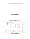
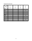
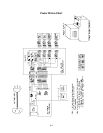
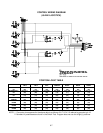
Control Panel Wires That Aren’t Part of Main JAMMA Harness
Function Wire Color P14- Function Wire Color P7-
4 Digital Ground Black 1 3 Digital Ground Black 1
+5 Volts Red 2 Unused Not Connected 2
Unused Not Connected 3/4/15 Unused Not Connected 3/4/15
4 Start Gray-White 5 3 Start Blue-White 6
4 Stick Up, Bit 0 Gray-Black 6 3 Stick Up, Bit 0 Blue-Black 7
4 Stick Down, Bit 1 Gray-Brown 7 3 Stick Down, Bit
1
Blue-Brown 8
4 Stick Left, Bit 2 Gray-Red 8 3 Stick Left, Bit 2 Blue-Red 9
4 Stick Right, Bit 3 Gray-Orange 9 3 Stick Right, Bit 3 Blue-Orange 10
4 Button A, Jump Gray-Yellow 10 3 Button A, Jump Blue-Yellow 11
4 Button B, Pass Gray-Green 11 3 Button B, Pass Blue-Green 12
4 Button C, Turbo Gray-Blue 12 3 Button C, Turbo Blue 13
4 Button D (N/U) Gray-Violet 13 3 Button D (N/U) Blue-Violet 14
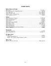
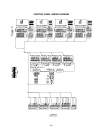
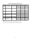
D.C. Power Source Voltage Limits
Function Range Limits ID Function Range Limits ID
Digital Circuits +4.90V to +5.10V +5V Audio, Lights -4.75V to -5.25V -5V
Audio, DBV +11.5V to +12.5V +12V NOTE: +5V is adjustable at the Power Supply