


70
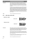
The first word of any instruction defines the instruction and provides any de-
finers and sometimes bit operands required by the instruction. All other oper-
ands (i.e., operand words) are placed in words after the instruction word, one
operand to a word, in the same order as these appear in the ladder symbol
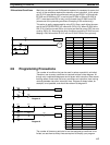
for the instruction. Although the SV for TIM and CNT are written to the left of
the symbol on the same line as the instruction, these are the only instructions
for which one line in the ladder symbol must be coded as two words (i.e., two
lines) in the mnemonic code. Also the TC number for TIMH(15) is placed on
a second line even though it is part of the instruction word. For all other in-
structions, each line of the ladder diagram will go into one word of mnemonic
code.
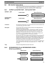
The address and instruction columns of the mnemonic code table are filled in
for the instruction word only. For all other words, the left two columns are left
blank. If the instruction word requires no definer or bit operand, the data col-
umn for it is left blank. It is a good idea to cross though the blank data col-
umn for all instruction words not requiring data so that the data column can
be quickly scanned to see if any addresses have been left out.
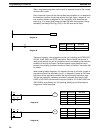
If an IR or SR address is used in the data column, the left side of the column
is left blank. If any other data area is used, the data area abbreviation is
placed on the left side and the address is place on the right side. If a con-
stant is to be input, the number symbol (#) is placed on the left side of the
data column and the number to be input is placed on the right side. Any num-
bers input as definers in the instruction word do not require the number sym-
bol on the right side. Remember, TR bits, once defined as a timer or counter,
take a TIM (timer) or CNT (counter) prefix.
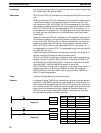
When coding an instruction that has a function code, be sure to write in the
function code, which will be necessary when inputting the instruction.
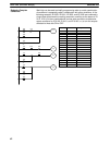
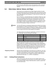
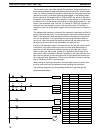
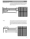
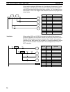
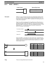
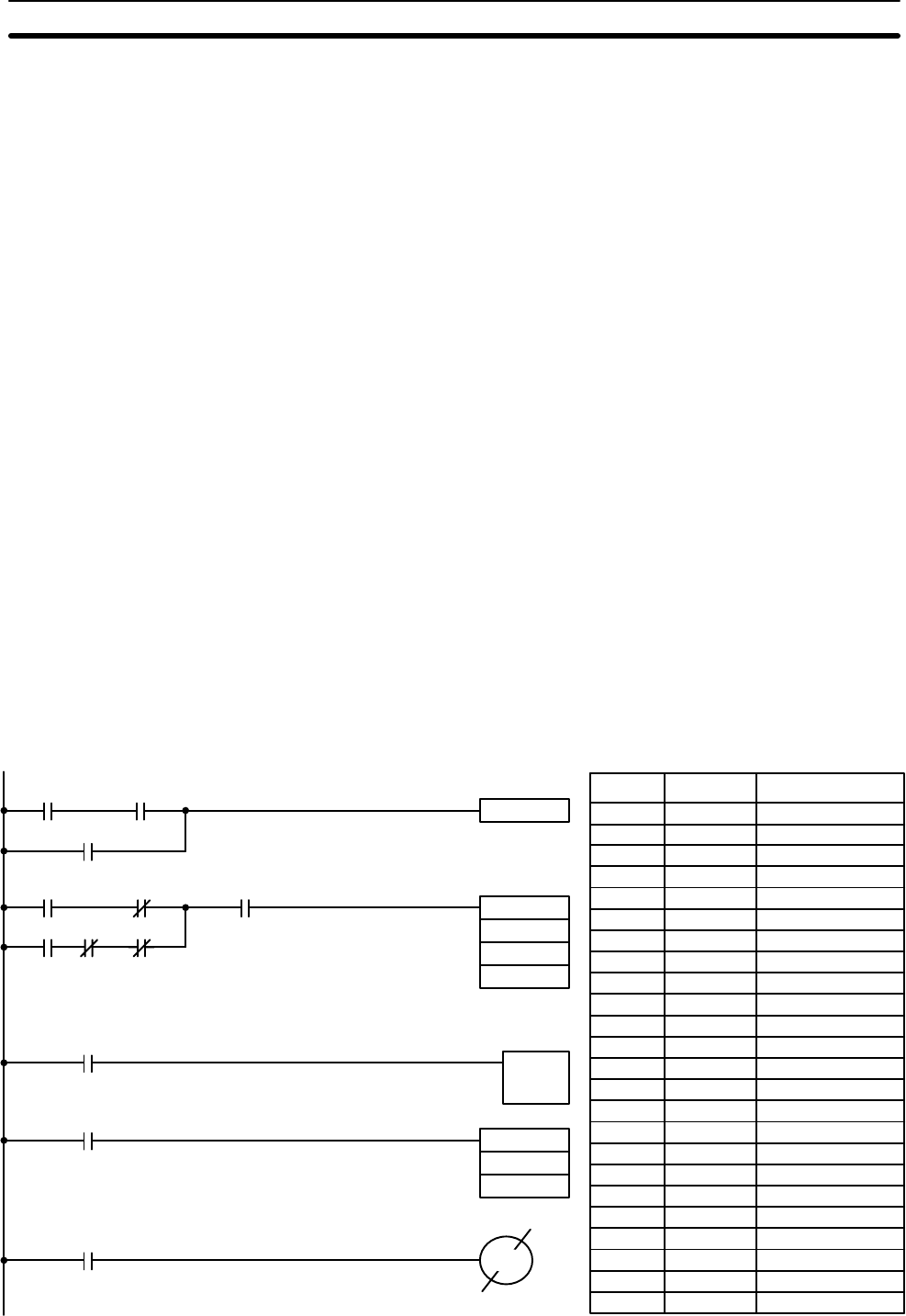
The following diagram and corresponding mnemonic code illustrate the
points described above.
TIM 00
# 0150
0003 0200
DIFU(13) 1500
0100
ADD(30)
#0001
0004
HR 0
MOV(21)
HR 0
HR 2
0006 0007 1505
TIM 00
1500
0002
00005
HR 015
0000 0001
Address Instruction Operands
0000 LD 0000
0001 AND 0001
0002 OR 0002
0003 DIFU(13) 1500
0004 LD 0003
0005 AND NOT 0200
0006 LD 0006
0007 AND NOT 0007
0008 AND NOT 1505
0009 OR LD
0010 AND 1500
0011 ADD(30)
# 0001
0004
HR 0
0012 LD 0005
0013 TIM 00
# 0150
0014 LD TIM 00
0015 MOV(21)
HR 0
HR 2
0016 LD HR 015
0017 OUT NOT 0100
Data Areas, Definer Values, and Flags Section 5-4