


13
The maximum number of available I/O bits is 16 (bits/word) times the number
of I/O words. I/O bits are assigned to input or output points as described in
Word Allocations
.
If a Unit brings inputs into the PC, the bit assigned to it is an input bit; if the
Unit sends an output from the PC, the bit is an output bit. To turn on an out-
put, the output bit assigned to it must be turned ON. When an input turns on,
the input bit assigned to it also turns ON. These facts can be used in the pro-
gram to access input status and control output status through I/O bits.
I/O bits that are not assigned to I/O points can be used as work bits, unless
otherwise specified in
Word Allocations
.
Input bits can directly input external signals to the PC and can be used in any
order in programming. Each input bit can also be used in as many instruc-
tions as required to achieve effective and proper control. They cannot be
used in instructions that control bit status, e.g., the OUTPUT, DIFFERENTI-
ATION UP, and KEEP instructions.
Output bits are used to output program execution results and can be used in
any order in programming. Because outputs are refreshed only once during
each cycle (i.e. once each time the program is executed), any output bit can
be used in only one instruction that controls its status, including OUT, OUT
NOT, KEEP(11), DIFU(13), DIFD(14), and SFT(10). If an output bit is used in
more than one such instruction, only the status determined by the last in-
struction will actually be output from the PC. See
5-12-1 SHIFT REGISTER -
SFT(10)
for an example of an output bit controlled by two instructions.
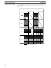
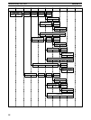
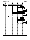
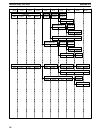
The maximum number of words available for I/O within the IR area is 10,
numbered 00 through 09. The remaining words (10 through 18) are to be
used for work bits. (Note that with word 18, only the bits 00 through 07 are
available for work bits although some of the remaining bits are required for
special purposes when RDM is used).
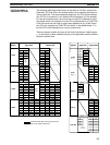
The actual number of bits that can be used as I/O bits is determined by the
model of the CPU and the PC configuration. There are different models of
Expansion I/O Units and Special I/O Units and I/O Link Units which can be
connected to any of the CPUs. Each CPU model provides a particular num-
ber of I/O bits and each Expansion I/O Unit, Special I/O Unit or I/O Link Unit
provides a particular number of I/O bits. Configuration charts for the possible
combinations of CPUs and Units are included later in this section. Refer to
those to determine the actual available I/O bits.
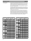
Within CPUs the I/O input words are always even numbered and the output
words are always odd numbered. The general rule when connecting Expan-
sion I/O Units to CPUs is that the first available word for the Expansion I/O
Unit (whether input or output or a combination) is one more than the last I/O
word of the CPU. If the Expansion I/O Unit is only either input or output (and
not both) then the I/O words provided by the Expansion I/O Unit are allocated
consecutively and the remaining words up to word 09 may be used for work
bits. If the Expansion I/O Unit provides both input and output words then the
words are allocated alternatively (input words always having even numbers)
until all I/O words provided by the Expansion I/O Unit are allocated. The re-
maining words up to word 09 may then be used for work bits. Note that when
a portion of an input word is not allocated to an input point then that portion
may be used for work bits.
I/O Words
Input Bit Usage
Output Bit Usage
Word Allocations
Internal Relay (IR) Area Section 3-3