


132
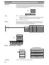
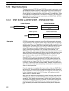
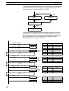
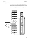
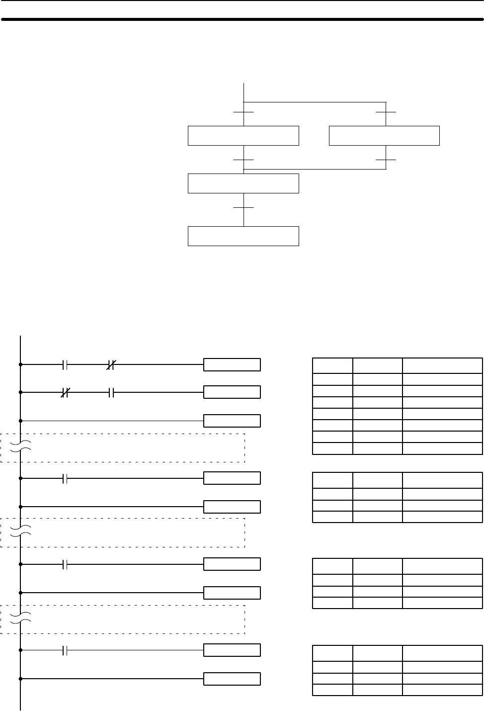
The following diagram demonstrates the flow of processing and the switches
that are used for execution control. Here, either process A or process B is
used depending on the status of SW A1 and SW B1.
Process A
Process C
End
SW A1
SW B1
SW A2
SW B2
SW D
Process B
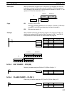
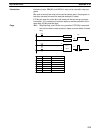
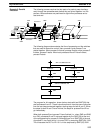
The program for this process, shown below, starts with two SNXT(09) that
start processes A and B. Because of the way 0001 (SWA1) and 0002 (SB
B1) are programmed, only one of these will be executed to start either proc-
ess A or process B. Both of the steps for these processes end with a
SNXT(09) that starts the step for process C.
0000 LD 0001
0001 AND NOT 0002
0002 SNXT(09) 1400
0003 LD NOT 0001
0004 AND 0002
0005 SNXT(09) 1401
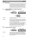
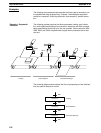
0006 STEP(08) 1400
SNXT(09) 1401
0002 (SW B2)
STEP(08) 1400
SNXT(09) 1402
STEP(08) 1401
SNXT(09) 1402
STEP(08) 1402
SNXT(09) 1403
STEP(08)
Process A
Process B
Process C
0003 (SW A2)
0004 (SW B2)
0005 (SW D)
Process A
started.
Process A
reset.
Process
C started.
Process B
reset.
Process
C started.
Process C
reset.
0001 (SW A1)
SNXT(09) 1400
0002 (SW B2)
0001 (SW A1)
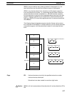
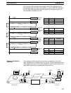
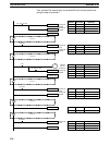
Address Instruction Operands
Address Instruction Operands
0100 LD 0003
0101 SNXT(09) 1402
0102 STEP(08) 1401
Address Instruction Operands
0200 LD 0004
0201 SNXT(09) 1402
0202 STEP(08) 1402
Address Instruction Operands
0300 LD 0005
0301 SNXT(09) 1403
0302 STEP(08)
Step Instructions Section 5-18