


32
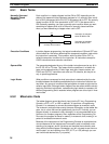
4-3-4 OUT and OUT NOT
The OUT and OUT NOT instructions are used to control the status of the
designated operand bit according to the execution condition. With the OUT
instruction, the operand bit will be turned ON as long as the execution condi-
tion is ON and will be turned OFF as long as the execution condition is OFF.
With the OUT NOT instruction, the operand bit will be turned ON as long as
the execution condition is OFF and turned OFF as long as the execution con-
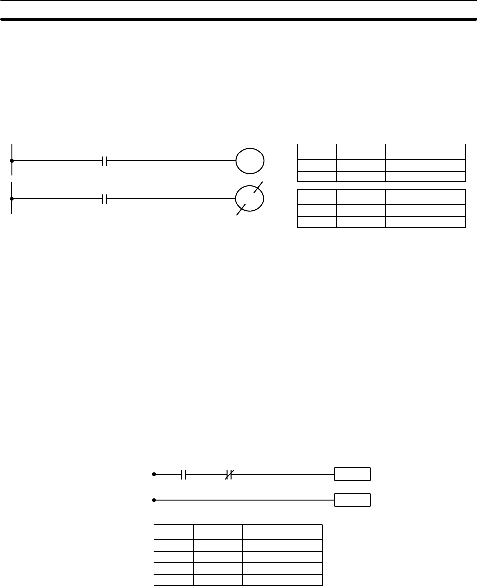
dition is ON. These appear as follows:
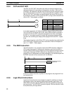
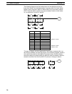
0000
0101
0100
0001
Address Instruction Operands
0000 LD 0000
0001 OUT 0100
Address Instruction Operands
0000 LD 0001
0001 OUT NOT 0101
In the above examples, bit 0100 will be ON as long as 0000 is ON and bit
0101 will be OFF as long as 0001 is ON. Here, 0000 and 0001 would be in-
put bits and 0100 and 0101 output bits assigned to the Units controlled by
the PC, i.e., the signals coming in through the input points assigned 0000
and 0001 are controlling the output points assigned 0100 and 0101, respec-
tively.
The length of time that a bit is ON or OFF can be controlled by combining the
OUT or OUT NOT instruction with timer instructions. Refer to Examples un-
der
5-11-1 TIMER - TIM
for details.
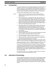
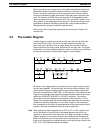
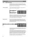
4-3-5 The END Instruction
The last instruction in any program must be the END instruction. When the
CPU cycles the program, it executes all instructions up to the first END in-
struction before returning to the beginning of the program and beginning exe-
cution again. Although an END instruction can be placed at any point in a
program, which is sometimes done when debugging, no instructions past the
first END instruction will be executed until it is removed.
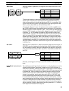
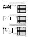
Instruction
0000 0001
END(01)
Program execution
ends here.
Address Instruction Operands
0500 LD 0000
0501 AND NOT 0001
0502 Instruction
0503 END(01) ---
If there is no END instruction anywhere in the program, the program will not
be executed at all.
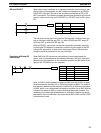
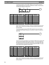
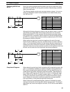
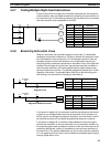
4-3-6 Logic Block Instructions
Logic block instructions do not correspond to specific conditions on the lad-
der diagram; rather, they describe relationships between logic blocks. The
AND LOAD instruction logically ANDs the execution conditions produced by
two logic blocks. The OR LOAD instruction logically ORs the execution condi-
tions produced by two logic blocks.
The Ladder Diagram Section 4-3