


ALARM HANDLING EXCEL 50/100/500/600/800
EN2B-0092GE51 R0512 46
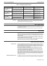
Operational status All datapoints can be switched from the 'automatic' to the 'manual' operational
mode. Each time the operating mode is changed, irrespective of the direction
involved, a critical alarm signal is generated. Both alarm signal texts are
preprogrammed and require no input from the user.
Remote (V2.0.x) (not with Excel 100C) If a manual override control is changed on a Distributed I/O module, an alarm
“overr.switch_manu” or “overr.switch_auto” is generated and the “manu” value is
transmitted.
Alarm suppression in manual mode Under controller firmware 2.06.02 and higher, the following datapoint alarms can be
suppressed for as long as the corresponding datapoints are in the 'manual override'
mode:
• min. and max. limit alarms (of analog datapoints, only);
• status alarms (of digital datapoints, only).
This alarm suppression is activated during CARE engineering by inserting the "at"
sign ("@") at the beginning of the descriptor text of the pseudo datapoint "Startup".
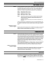
Benefits:
As long as this alarm suppression is in effect, the repair or replacement of defective
and/or malfunctioning (flickering) inputs (resulting e.g. from sensor breakage,
sensor short-circuiting, defective alarm switches, etc.) can be performed while the
corresponding datapoint is in the "manual override" mode.
NOTE: Only when using XFI 2.1.0 SIM1 will the event behavior and visualization
behavior be identical to that of Honeywell Deltanet controllers.
System Alarms
Operating errors that occur in a control unit or during communication with other
Excel 50/100/500/600/800 units are recognized and displayed by the computer
module. These alarm signals can relate, for example
, to a defective module, the
need to change the buffer battery (data protection), or the presence of one digital
output module too many (maximum 10). These alarm signal texts are
preprogrammed. They are always critical alarms.
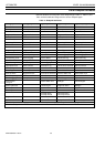
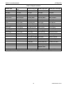
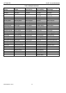
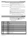
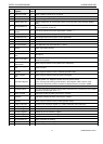
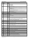
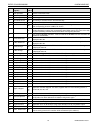
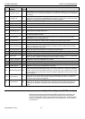
Table 20. System alarms
Alarm
no.
alarm text
English)
cond.
code #
cause/reason
1 AI Module Defect 25 Maximum conversion time was exceeded while testing ADC (defect on an AI card).
2 AI 0 Volt Error 24
While measuring GND voltage on an AI card, one value greater than 0.5 V was measured
(AI card defect).
3 AI 5 Volt Failure 23
While measuring the 5-V reference voltage on an AI card, one value greater than 5 V or
smaller than 4.5 V was measured (AI card defect or incorrect power supply of AI card).
4 MAX 2 alarm 2 Alarm limit for AI-, PA points
5 MAX 2 normal 76 Alarm limit for AI-, PA points
6 MAX 1 alarm 1 Alarm limit for AI-, PA points
7 MIN 2 alarm 4 Alarm limit for AI-, PA points
8 MIN 2 normal 78 Alarm limit for AI-, PA points
9 MIN 1 alarm 3 Alarm limit for AI-, PA points
10 MAX 1 normal 75 Alarm limit for AI-, PA points
11 MIN 1 normal 77 Alarm limit for AI-, PA points
12 Alarm memory full 22
1) After starting the Field I/O Task with the parameter "INIT", the default datapoint
description couldn't be installed because USX didn't provide enough storage space for
sending CNAP telegrams.
2) Alarm send buffer full.
13 Alarm 6 Alarm condition control for DI , PD points.