


ATTRIBUTES EXCEL 50/100/500/600/800
EN2B-0092GE51 R0512 32
• As soon as an alarm occurs (e.g. through exceeding a limit value), the attribute
"Point in Alarm" is set to "Yes". The attribute is immediately set back to "No"
when the limit value returns to normal.
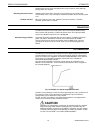
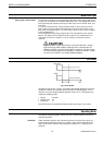
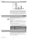
Pulse Duration
The attribute "Pulse Duration" is used for the pulsed subtypes of the digital output
(i.e. "Pulse 1") and flexible datapoints of the type "Pulse 2". It defines the duration
between coming and going edge of a pulsed signal. The values for this attribute can
vary from 1 to 255 seconds; the resolution is 1 second. The default value is 1
second.
NOTE: After a power failure or disconnection of the controller, the “Pulse 1” and
“Pulse 2” outputs will resume their last output pulse behavior before the
outage.
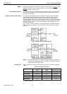
Safety Position (XFx822x, XFx824x, and XFx830x modules)
The analog output modules XF822x/XFL822x/XFLR822x, the relay output modules
XFL824x/XFL824x/XFLR824x and the mixed I/O modules XF830x/XFU830x support
the “Safety Position” attribute, which can be set in the CARE datapoint editor.
The modules will put the outputs into the safety position as soon as communication
with the Excel 800 CPU is lost.
The XF822x/XF824x modules detect this lost communication once no more polls
are received from the Excel 800 CPU for more than one second.
The XFL822x/XFL824x and XF830x/XFU830x modules detect this lost
communication once no more polls are received from the Excel 800 CPU within the
heartbeat time of the module.
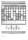
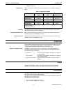
XF822x/XFL822x –”The following attribute options are provided:
• “0%” equals 0 Vdc or 2 Vdc (0…11 Vdc or 2…11 Vdc characteristic)
• “50%” equals 5 Vdc or 6 Vdc (0…11 Vdc or 2…11 Vdc characteristic)
• “100%” equals 10 Vdc
• “Remain in last position” (this is the default setting).
XF824x/XFL824x and XF830x/XFU830x –”The following attribute options are
provided:
• “Off (logical)”
• “On (logical)”
• “Remain in last position” (this is the default setting).
NOTE: When the XFL822x/XFLR822x and XFL824x/XFLR824x modules are
used with non-Excel 800 controllers, the Safety Position can only be set
in the L
ONWORKS NV settings in CARE, and not in the CARE datapoint
editor.
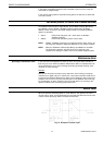
Scaling Factor
Input pulses from utility meters (gas, water, heat, etc.) can be connected to the
totalizer inputs using the attribute "Scaling Factor". The pulses supplied by the
meters are multiplied by the scaling factor and are then ready to be read as pure
consumption values. The "Scaling Factor" thus always indicates the value of each
pulse received. The adjustable range is 0.0 through 100,000,000.0,
The number of decimal places depends on the selected engineering unit.
Example: A heat meter supplies 10 pulses per kWh "consumed". Accordingly, the scaling
factor (= value of a pulse) is 0.1 kWh/pulse.