


Installation - 2
33
External
Trigger
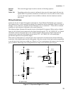
This external trigger input is used to start the cell forming sequence.
Power Fail
Depending on how the system is configured, when true, this input signal will cause the
Agilent MCCD to perform a shutdown, at which time it saves its state for a later restart.
A power fail output signal is also available to indicate when the shutdown state has
been saved.
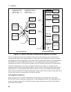
Wiring Guidelines
Connection for the 16 digital I/O signals are through two 10-pin Phoenix/Weidmuller style connectors.
The connectors have screw terminals for making wire connections and are detachable. Digital I/O lines 0
through 7 are on connector 1; digital I/O lines 8 through 15 are on connector 2. There are two common
terminals on each connector for ground or the return connection.
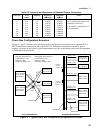
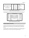
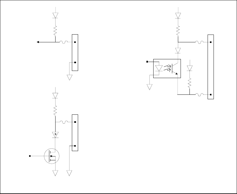
The following figure illustrates the internal circuits of the digital I/O connector. When used as a digital
input (A), the external circuit connected to the digital input pin can be TTL, AS, CMOS, HC, or a simple
switch that connects the digital input to the common terminal. When used as a digital output (B) the
external circuit connected to the output pin can also be TTL, AS, CMOS, HC or a warning light,
provided the light has an external bias supply.
When used as isolated pairs (C), each pin pair can be connected to external circuits with the following
restrictions: Only adjacent pairs can be used together. Only the even pin of each pair can be programmed
to set the logic level as low true or high true. When Low True is programmed, the output is true when the
pins are shorted. When High True is programmed, the output is true when the pins are open.
4.7K
+5V
Dig In signal
Odd or Even Pin
Dig Out signal
4.7K
+5V
Dig Out signal
Isolated
A. Digital Input
4.7K
+5V
B. Digital Output
4.7K
+5V
C. Isolated Output
DIG I/O
Connector
Odd or Even Pin
DIG I/O
Connector
Even Pin
Adjacent
Odd Pin
Common
Common
Figure 2-3. Equivalent Digital I/O Circuits