


2 - Installation
32
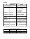
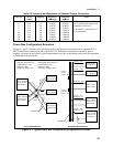
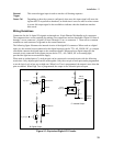
Digital Connections
Each Agilent E4370A MCCD mainframe has a 16-bit digital I/O port. Digital I/O configuration can be
done with the Agilent MCCD Configuration Screens as described in chapter 3 or with the Agilent MCCD
User Interface as described in chapter 4. All pins do not have to be configured the same. Some can be
used as isolated outputs while others are single ended I/O. The functions can also be mixed, some pins
can be general purpose I/O while others have a specific purpose. The polarity of a bit can also be
configured as either high true or low true. The following list documents the types of digital I/O
configurations:
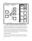
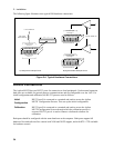
General Purpose I/O
General purpose I/O programs the digital I/O as a passthrough function that allow input or output signals
on the digital connector to be directly controlled with API programming commands. These signals have
no effect on the cell forming sequence.
Digital
Output
When configured as outputs, each line is driven by an internal open collector
transistor. Output lines are capable of driving either TTL compatible inputs, or high
power loads such as solenoids, indicator lights, and relays. These are 24 V/ 300mA
compatible open-collector outputs.
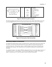
Digital Input
When configured as inputs, each line can be driven by an external source. All lines are
TTL compatible inputs, with built in pull-ups to 5 V to facilitate contact and switch
closure style inputs.
Digital In/Out
When configured as in/out, each line can be used as both an input and an output.
Programming the line high allows an external device to drive the line. Programming
the line low drives the line low. Reading the line returns the actual state of the line.
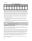
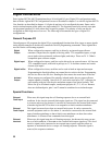
Isolated
Output
When outputs are configured for optically isolated mode, they are open-collector
outputs capable of sinking 1.6mA at 0.4V, and can be used up to 24V. Adjacent pin
pairs starting with pin 0 are the plus and minus output of an optical isolator. This
allows for up to 8 isolated outputs, on adjacent pin pairs 0-1, 2-3, 4-5 etc. Because
these are dedicated pairs, pins 1 and 2 cannot be combined as an isolated output.
Special Functions
External
Fault Input
When true, this signal stops the cell forming sequence due to an external fault
condition. It also sets the external fault output signal true. This signal can be connected
to a sensor such as a fire detector. It can also be connected to the external fault output
of another Agilent MCCD so that it can respond to a fault in another mainframe.
External
Fault Output
This signal is asserted true when an external fault occurs. It can be connected to
external equipment such as a fire alarm. It can also be connected to the external fault
input of another mainframe so that a fault in one mainframe can shut down other
mainframes. A cfProtectClear command clears this signal.
External
Interlock
When true, this signal stops the cell forming sequence, but because the stop was not
due to a fault condition, it does not set the external fault output signal true. This level-
sensitive signal can be connected to an external stop or pause switch to allow an
operator or mechanical device to stop a cell forming sequence. When the signal is
removed, the sequence continues.