


2 - Installation
26
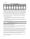
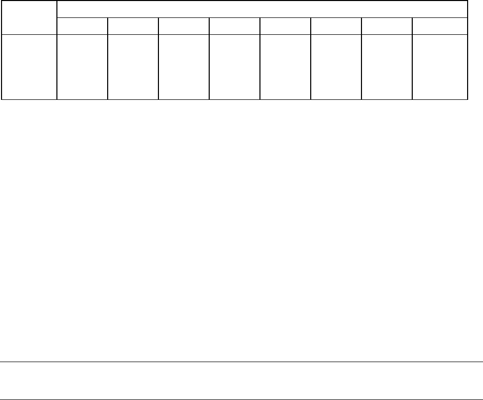
Table 2-4. Channel Configuration
Card Connector Number
Number 1234567 8
1
1 - 8 9 - 16 17 - 24 25 - 32 33 - 40 41 - 48 49 - 56 57 - 64
2
65 - 72 73 - 80 81 - 88 89 - 96 97 - 104 105 - 112 113 - 120 121 - 128
3
129 - 136 137 - 144 145 - 152 153 - 160 161 - 168 169 - 176 177 - 184 185 - 192
4
193 - 200 201 - 208 209 - 216 217 - 224 225- 232 233 - 240 241 - 248 249 - 256
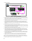
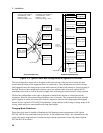
Power connections on each Agilent 64-Channel Charger/Discharger Card are through eight 37 pin D-
subminiature connectors. These connectors allow for shielding and strain relief. Corresponding sense
connections are also available on the connectors. Refer to Table 2-2 for information about ordering the
mating connectors. As indicated in the table, mating connectors accept wire sizes from AWG 24 up to
AWG 18, depending on the type of connector that you are using. You must wire up the mating connector
to make your wire connections. Install the mating connector on the front of the charger/discharger card
when complete. Refer to Appendix D for detailed pinout assignments of the front panel connectors.
If specific channels are not being used, you can configure them to be inactive. Inactive channels are
open-circuited. Note that there are two ways to configure the channel outputs, each having different
effects when the unit is powered on.
♦ If you configure the channel outputs using the cfSetOutputConfig() function (see chapter 6), the
settings are NOT saved in non-volatile memory. Each time you power up the unit, you must
reprogram the settings.
♦ If you configure the channel outputs using the Sequence setup page in the Agilent MCCD User
interface (see chapter 4), the settings ARE saved in non-volatile memory. The unit will wake up with
those settings when it is powered up.
NOTE: If the mainframe has empty card slots, the channels that are normally reserved for those
card slots will be treated as inactive channels.
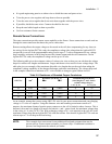
Voltage Drops and Wire Resistance
Agilent E4374A Charger/Discharger Cards have a maximum of 5.5V and 2A available at the power
connector of each channel. Agilent E4375A Charger/Discharger Cards have a maximum of 6V and 3A
available at the power connector of each channel.
This means that at the rated output of 5V, the Agilent E4374A cards will tolerate up to a 0.5 volt drop,
and the Agilent E4375A cards will tolerate up to a 1.0 volt drop in the load leads due to wire resistance,
probe resistance, connector resistance, etc. Higher voltage drops will reduce the available voltage at the
cell. Proper wiring design including using larger gauge wires and low-resistance fixture contacts can
minimize voltage losses in the wiring and maximize the available voltage for charging the cells.
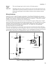
The length of the leads from the power connector to the cells is determined by how much voltage drop
your system can tolerate. The voltage drop is directly determined by the wire, connector, and probe
resistance (see table 2-5). Refer to Remote Sense Connections for more information.
To optimize performance and minimize the possibility of output instability and output noise, please
observe the following guidelines: