


General Information - 1
21
When power fails, the power bus is also disconnected from the Agilent MCCD because of the bias
powered relays inside the Agilent MCCD. Thus, should a power failure occur which causes the Agilent
MCCD to lose ac power, in order to provide for safety, these internal relays would be disengaged and any
further charging or discharging would stop, even if the power bus were still powered and active.
Also, should a power failure occur which does not effect the Agilent MCCD but which causes the power
bus to drop in voltage, this will be detected by the Agilent MCCD as a power bus undervoltage condition
and the relays will open, thus preventing any further charging or discharging of connected cells.
Remote Programming Interface
The remote programming interface to the Agilent MCCD is through a LAN-based TCP/IP
communication protocol. The connection to the LAN is through a standard 8-pin 10Base-T connector on
the rear panel, which must first be configured according to the directions in chapter 3. The LAN
communication protocol is implemented in two ways:
Application Programming Interface (API)
The application programming interface runs under Windows 95 or Windows NT 4.0 using supplied C-
language function calls. These function calls are documented in chapters 5 and 6, and provide the most
comprehensive method of controlling the Agilent MCCD. The API interface is the preferred method of
control when the Agilent MCCD is connected to a remote computer as part of an automated
manufacturing process.
Web Accessible Agilent MCCD User Interface
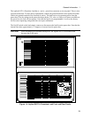
The Agilent MCCD has a built-in web server with a graphical user interface that is accessed through
standard web browsers such as Netscape Navigator version 3.03 and up or Microsoft Internet Explorer
version 3.02 and up. This Agilent MCCD User Interface allows monitoring of individual cell state,
measuring cell voltages and currents while the test is running, and also complete monitoring and control
of test status. The Agilent MCCD User Interface is the preferred method of control when evaluating the
test system, prototyping a process, or debugging a program.
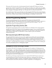
Example of a Cell Forming Process
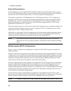
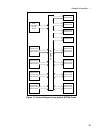
The Agilent E4370A MCCD is designed to be the integral part of a complete cell forming process as
shown in Figure 1-7. As shown in the figure, many of the previously mentioned protection and external
signal capabilities of the Agilent E4370A MCCD are implemented using the digital I/O connections. The
serial ports on the back of the Agilent MCCD are used to control local peripherals directly from the host
computer. The remote programming interface to the Agilent MCCD lets you seamlessly integrate all of
these capabilities into the cell forming process.
The following cell forming example describes how an Agilent E4370A MCCD may be used to run a
semi-automated process where the only human actions required are: entering data with a barcode
scanner, loading and unloading a test fixture, and manually starting the cell forming process. Chapters 5
and 6 describe all of the function calls that are available to implement a cell forming process.