


A - Specifications
116
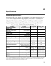
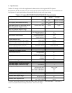
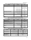
Tables A-2 through A-4 list the supplemental characteristics of the Agilent MCCD System.
Requirements for the external power bus source are also listed. Characteristics are not warranted but are
descriptions of typical performance determined either by design or by type testing.
Table A-2. Agilent E4370A/E4374A/E4375A MCCD Characteristics
Parameter Condition Value
E4374A E4375A
Ah Capacity Measurement Accuracy
% of reading + offset ≤ 2 A:
> 2 A:
± (0.1% +1mAh/h)
N/A
± (0.10% +1.5mAh/h)
± (0.15% +1.5mAh/h)
Wh Capacity Measurement Accuracy
% of reading + offset ≤ 2 A:
> 2 A:
± (0.1% +5mWh/h)
N/A
± (0.10% +7.5mWh/h)
± (0.15% +7.5mWh/h)
Maximum Deviation of Measured Current
from Programmed Output Current
constant current mode
± 2 mA ± 3 mA
Maximum Deviation of Measured Voltage
from Programmed Output Voltage
constant voltage mode
± 2 mV
ac Resistance Measurement
maximum measurable:
max. time/cell to measure:
time for 256 cells:
1 Ω
1 s
~ 5 min.
dc Resistance Measurement
maximum measurable:
max. time/cell to measure:
time for 256 cells:
1 Ω
1 s
~ 5 min.
Voltage Output Noise
(at MCCD connector; bandwidth = 20Hz - 20MHz)
rms
peak-to-peak
30 mV
100 mV
Current Output Noise
(at MCCD connector; bandwidth = 20Hz - 20MHz)
rms
peak-to-peak
1 mA
10 mA
Maximum Current Overshoot/Undershoot
(from first applied programmed current level)
with current <50 mA
with current >50 mA
± 15 mA for up to 500 ms
5 % for up to 5 ms
Maximum Voltage Overshoot/Undershoot
± 25 mV
Maximum Current Risetime
0.1 s
Minimum Programming Current
charging and discharging 25 mA
Measurement Interval
for data logging
for sequence tests
for probe check/channel
1 s
1 s
1 s
Step Time
maximum
minimum
resolution
596 hours
7 s
1 s
Maximum Readings in Data Buffer
349,504
Maximum Sequence Length
596 hours
Maximum Number of Steps in Sequence
100
Maximum Number of Defined Groups
per mainframe 8
ac Input Line Requirements
input voltage range
input frequency range
maximum input power
max. current @ 100/120Vac
max. current @ 220/240Vac
95 Vac - 250 Vac
47 Hz - 63 Hz
300 W
4 A
2 A
Maximum Sense Probe Resistance
1
1 kΩ
Auxiliary bias output power
max. @ 5 to 24V/0.42 to 2A 10 W
Auxiliary bias output voltage
max. @ 0 to 0.42A
min. @ 0 to 2 A
24 V
5 V
Auxiliary bias output current
max. @ 5 V output
min. @ 24 V output
2 A
0.42 A
1
To measure output probe resistance accurately there must be 50 mV between the +/− power leads and the +/− sense leads. To
measure sense probe resistance accurately, there must be 100 mV of cell voltage.