


1 - General Information
18
Cell Resistance
In addition to continuous voltage, current, and capacity measurements, the Agilent MCCD can also
measure ac and dc cell resistance. This measurement is available on command when a sequence is not
running, or as its own step in the forming sequence.
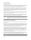
The Agilent MCCD measures the ac cell resistance by first disconnecting the charge/discharge circuits
from all cells. An ac waveform generator in the Agilent MCCD mainframe is connected sequentially to
each cell. The ac waveform generator momentarily passes a small excitation current through each cell
while the measurement system measures the cell’s output voltage and current. By using a narrow band
tuned filter and computing the magnitude and phase angle of voltage relative to current, an ac resistance
measurement of the cell can be made. This method is very similar to the method used by LCR meters.
Since this measurement happens sequentially for each channel, the other channels stay at rest during this
test.
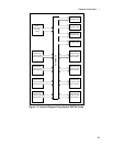
The Agilent MCCD measures the dc cell resistance by first disconnecting the charge/discharge circuits
from all cells. A pulse generator in the Agilent MCCD mainframe is connected sequentially to each cell.
The pulse generator passes a short-duration pulsed current through each cell while the measurement
system digitizes the cell voltage and current using a high accuracy, high-speed A/D converter. Using
proprietary algorithms to calculate the change in voltage relative to the change in pulsed current, a dc (or
pulse) resistance measurement of the cell can be made. Since this measurement happens sequentially for
each channel, the other channels stay at rest during this test.
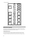
Probe Resistance
Probe resistance measurements can also be performed. The Agilent MCCD uses the remote sense to
measure the resistance of both the power and sense probes. Probe resistance measurements can be made
on command when a sequence is not running.
The measured probe resistance is the total resistance in the signal path, which includes wiring resistance,
probe resistance, and the resistance of any connectors in the signal path. For the sense probe
measurement, the resistance measurement includes the internal scanner resistance, which is typically
1000 ohms. The power and sense probe measurements return the actual measured value in ohms.
In addition to the on-command probe resistance measurements, the probes are continuously checked
while the sequence is running. See chapter 5 under “Probe Check” for more information about probe
check verification.
Data Logging
During a charge/discharge sequence, the Agilent MCCD is constantly making voltage, current, and
capacity measurements. Instead of logging each and every measurement into a data buffer, the data
logging can be controlled so that only critical measurements are logged to the data buffer. This is called
event-based data logging, which means that whenever an important event occurs, a data log record will
be written into the data buffer. Buffer memory is used most efficiently when only critical measurements
are stored.