


Installation - 2
27
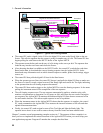
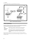
♦ It is good engineering practice to either twist or shield the sense and power wires.
♦ Twist the power wires together and keep them as short as possible.
♦ Twist the sense wires together but do not twist them together with the power wires.
♦ If possible, shield the sense wires. Connect the shield to the case.
♦ Keep the total cable length as short as possible.
♦ Use low resistance fixture contacts.
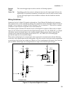
Remote Sense Connections
The sense connections provide remote sense capability at the fixture. Sense connections on each card are
through the same connectors that house the power connections.
Remote sensing allows the output voltages to be sensed at the cell, thus compensating for any losses in
the wiring. On the Agilent E4374A cards, the compliance voltage (the voltage that the Agilent MCCD
can provide in excess of the programmable rating) can be up to 5.5 volts to compensate for any voltage
drop caused by resistance in the wiring between the channel output and the cell connections. On the
Agilent E4375A cards, the compliance voltage can be up to 6.0 volts.
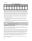
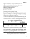
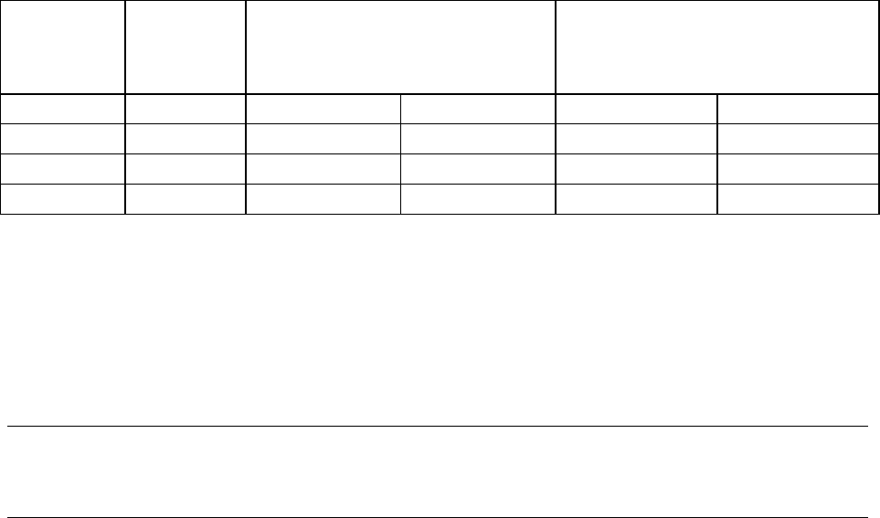
The following table gives the resistance values of various wire sizes so that you can calculate the voltage
drops for various wire lengths and diameters. Larger and shorter wires result in lower voltage drops. The
table also gives an example of the maximum allowable wire lengths that can be used when taking the
compliance voltage capability of the charger/discharger cards into consideration. The voltage drop used
in the example is based on a minimum of 4.1 volts available to charge a typical lithium ion cell.
Table 2-5. Resistance of Stranded Copper Conductors
AWG No. mm
2
Resistance (at 20 deg. C)
Ω
ΩΩ
Ω/m Ω
ΩΩ
Ω/ft
Maximum length in meters
(total length of + and - leads)
to limit voltage drop to:
1.4 V @ 2A 1.9 V @ 3A
18 0.825 0.022 0.0066 31 28
20 0.519 0.034 0.0105 20 18
22 0.324 0.055 0.0169 12 11
24 0.205 0.087 0.0267 8 7
As an example, assume that you are using AWG #24 wire for your power connections and your charging
voltage is 4.1 volts at 2 amperes. Using this diameter wire and assuming a maximum current of 2
amperes, the maximum distance from the power connector to the cell is limited to about 4 meters. This is
because with a total wire length of 8 meters for both the + and − power leads, the maximum voltage drop
in the wiring is 1.4 volts (2A X 0.7
Ω). With a charging voltage of 4.1 volts required at the cell, this is the
maximum voltage drop that an Agilent E4374A card can tolerate. Note that the Agilent E4375A card can
tolerate up to a 1.9 volt drop in the load wiring.
NOTE: This example does not account for any additional lead path resistance that may be
present such as fixture contact resistance, or fixture relays. If additional resistance is
present, lead length must be reduced yet further.