Section 2 – Cabinet Conversion
© 2004 GLOBAL VR
®
, INC.
040-0050-01 Rev. A 10/29/2004 Page 17 of 48
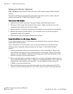
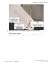
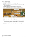
3. Set jumper J8 on the Jamma conversion board to pins 1 and 2 for stereo, or pins 1 and 3
for mono audio, depending on how your cabinet audio is set up.
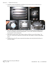
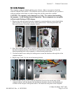
4. Place the boards next to each other in the service tray where you removed the old boards.
Make sure that the Jamma connector on the Jamma wire harness can reach the Jamma
Conversion Board before securing the boards to the cabinet.
5. Secure the boards with wood screws in the plastic feet.
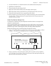
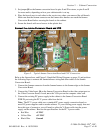
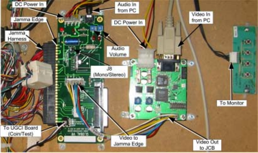
Connect the Jamma Conversion Board and UVC
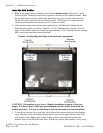
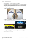
Figure 2. Typical Jamma Conversion Board and UVC Connections
Refer to the figure above, and Figure 5, Simplified Wiring Diagram, on page 43, and perform
the following steps to connect the Jamma harness wiring and other cables to the Jamma
Conversion Board:
1. Connect the Jamma connector from the Jamma harness to the Jamma edge on the Jamma
Conversion Board.
2. Connect the Video Input, J4 on the Jamma Conversion Board to the video output port on
the Video Converter board, if used, or to the VGA port on the computer video card.
3. Connect the existing PC power supply in the cabinet to the Jamma Conversion Board
PWR IN port using the PC Y-power cable from the kit.
Note: The PC Y-power cable uses a standard PC power supply connection found on
most DC power supplies used in arcade cabinets. If your existing power supply does not
have this type of connector, you will need to splice the Y-Power cable into the power
supply on the cabinet. Here are the specifications for the PC Y-power cable:
• Red Wire +5 VDC
• Yellow Wire +12 VDC
• Black Wire Ground


