


Verification and Calibration - B
67
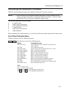
Performing the Verification Tests
The following procedures assume you understand how to operate the ac source from the front panel as
explained in Chapter 4.
When performing the verification tests from a GPIB controller, you may have to consider the relatively
slow settling times and slew rates of the ac source as compared to computer and system voltmeters.
Suitable WAIT statements can be inserted into the test program to give the ac source time to respond to
the test commands.
Perform the following tests for operation verification in the order indicated.
1. Turn-On Checkout
2. Voltage Programming and Measurement Accuracy
3. Current Measurement Accuracy
Turn-On Checkout Procedure
Perform the Turn-On Checkout as directed in Chapter 3.
NOTE: The ac source must pass turn-on selftest before you can proceed with the verification
tests.
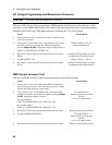
AC Voltage Programming and Measurement Accuracy
This test verifies the voltage programming, GPIB measurement, and front panel meter functions. Values
read back over the GPIB should be the same as those displayed on the front panel.
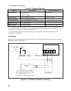
If more than one meter or if a meter and an oscilloscope are used, connect each to the sense terminals by
separate leads to avoid mutual coupling effects.
Action Normal Result
1. Make sure the ac source is turned off. Connect the DVM and ratio
transformer as shown in the test setup in Figure B-1.
2. Turn on the ac source with no load. In the Output menu, execute
the *RST command to reset the unit. Enable the output by
pressing Output On/Off. Program the output voltage as follows:
VOLT 300, FREQ 45, SHAPE:SIN, CURR 1
CV annunciator on.
Output current near 0.
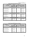
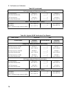
3. Record voltage readings at the DVM
1
and on the front panel
display.
Readings within specified High
range limits (300 V/45 Hz).
4. Program FREQ 400
5. Record voltage readings at the DVM
1
and on the front panel
display.
Readings within specified High
range limits (300 V/400 Hz).
4. Program FREQ 1000, CURR:PEAK 40
7. Record voltage readings at the DVM
1
and on the front panel
display.
Readings within specified High
range limits (300 V/1 kHz).
1
Multiply the DVM reading by the transformer ratio if a ratio transformer is used.