


General Information - 1
19
CAUTION: Programming the ac source output impedance into a load with a low impedance can
cause output voltage instability, which may damage the ac source. Stability MUST
be maintained when operating the ac source with programmable resistance or
inductance.
To check for stability, monitor the output voltage with an oscilloscope. Instability exists
if a 5kHz to 20kHz oscillation, which is dependent upon the ac source’s programmed
inductance and the capacitance of the load, is present at any time during the following
procedure.
1. When programming inductance, it is recommended that you first add a series
resistance either by programming the output resistance to 1 ohm or by adding an
equivalent external resistor.
2. Slowly program the inductance to the desired level while monitoring the output for
any voltage instability. Do not proceed any further if the output shows any signs of
instability.
3. If less output resistance is required, slowly start lowering the resistance while
monitoring the output for any voltage instability. Do not proceed any further if the
output shows any signs of instability.
If you cannot achieve satisfactory results with this procedure, disable the output
impedance control and use an external impedance network.
Rms voltage regulation can be used in conjunction with programmable output impedance to regulate the
rms value of the ac component of the output voltage when programmed impedances cause distortion with
nonlinear loads or reduced output voltage due to regulation effects.
Note that real-time voltage regulation will permit the load current to cause output voltage degradation
based on the programmed impedance and current drawn from the source, whereas rms regulation will
reestablish the rms value at the programmed level.
Output Coupling
Ac output coupling mode mimics a transformer-coupled output, working to maintain zero average
output voltage. This means that the output tries to remove any dc content on the output, whether the dc
content is generated from a programmed offset or results from transients with dc content. The ac output
coupling has a corner frequency of about 2 Hz, which will not prevent transient waveforms that may have
short-term dc content, but will regulate the waveform back to an average value of zero volts in the steady
state.
Dc output coupling mode is used to generate dc offset voltages or output transients that have net dc
components. In either mode of operation, the maximum voltage that the ac source can output is limited to
425 V peak.
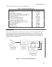
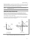
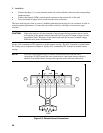
The ac capability of the output is limited by VA (volt-amperes) rather than power (watts). The amount of
VA available to a load can be determined by examining figure 1-2. Full output VA is available with no
limitations except for the boundaries imposed by the maximum rms voltage of 300V, and the maximum
rms current, which is model-dependent. Note that large peak power transients can be delivered by the ac
source as earlier described under "Peak Current Capability"(Appendix A documents the ac source’s
specifications and supplemental characteristics.)