


General Information - 1
17
♦ as voltage increases, the I
peak
setting needs to be decreased.
♦ as frequency increases, the I
peak
setting can be increased.
♦ as load resistance decreases, the I
peak
setting needs to be decreased.
Note that the purpose of programming the I
peak
current is to prevent the unit from activating its internal
protection mode as a result of exceeding the SOA limits, and turning the output off. These initial settings
may have to be reduced if the SOA circuit trips when the output is turned on. Sometimes trial and error
must be used to arrive at the proper values of I
peak
.
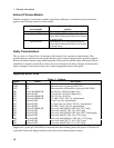
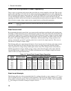
Table 1-4. Recommended I
peak
Settings as a Function of Loop Capacitance
Capacitance in µF
I
p
eak
setting
127 V 254 V
≤ 1100
500 80 A
1200 - 60 A
1700 700 50 A
5000 1000 45 A
> 5000 > 1000 < 45 A
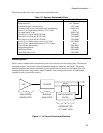
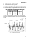
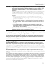
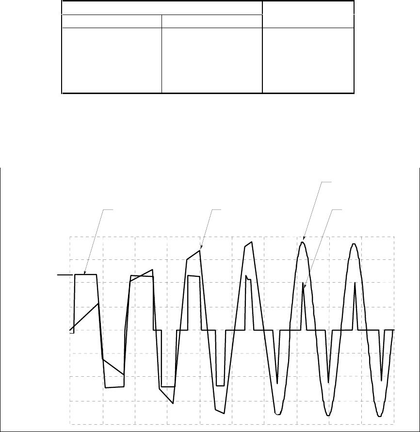
The following waveform illustrates the inrush current capability of the ac source. The peak current is
limited during inrush in accord with table 1-3 to keep the ac source from turning its output off. Note that
the output current waveform returns to its normal shape when the current drops below the peak current
limit setting.
Figure 1-3. Peak Inrush Current Example
0
I PEAK=45A
CURRENT
WAVEFORM
VOLTAGE
WAVEFORM
VOLTAGE IS
UNDISTORTED
PEAK CURRENT
< 45 A
(115 Vrms)