


Installation - 2
27
Remote Sensing and OVP Considerations
In remote sense applications, the voltage drop in the load leads subtracts from the available load voltage
(see "Remote Sensing Capability" in appendix A). As the ac source increases its output to overcome this
voltage drop, the sum of the programmed voltage and the load-lead drop may exceed the ac source’s
maximum voltage rating. This may trip the OV protection circuit, which senses the voltage at the output
terminals, not at the load. When using remote sensing, you must program the OVP trip voltage high
enough to compensate for the voltage drop between the output terminals and the load.
NOTE: If the load causes the peak current limit circuit to become active, voltage transitions on
the output may cause nuisance tripping of the OVP circuit.
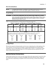
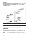
Trigger Connections
The BNC trigger connectors on the rear panel let you apply trigger signals to the ac source as well as
generate trigger signals from the ac source. The electrical characteristics of the trigger connectors are
described in appendix A. More information on programming external triggers is found in Chapter 4 of
the ac source Programming Guide.
Trigger IN Allows negative-going external trigger signals to trigger the ac source.
Trigger OUT Generates a negative-going pulse when the selected transient output has occurred.
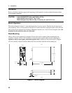
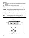
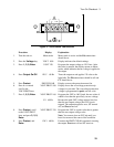
Digital Connections
This connector, which is on the rear panel, is for connecting the fault and the inhibit signals. The fault
(FLT) signal is also referred to as the DFI signal in the front panel and SCPI commands. The inhibit
(INH) signal is also referred to as the RI signal in the front panel and SCPI commands.
The connector accepts wires sizes from AWG 22 to AWG 12. Disconnect the mating plug to make your
wire connections. The electrical characteristics of the digital connectors are described in appendix A.
More information on programming the digital connectors is found in Chapter 4 of the ac source
Programming Guide.
NOTE: It is good engineering practice to twist and shield all signal wires to and from the digital
connectors
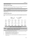
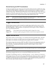
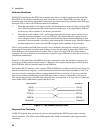
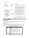
The following examples show how you can connect the FLT/INH circuits of the ac source.
In example A, the INH input connects to a switch that shorts pin + to pin ⊥ whenever it is necessary to
disable output of the unit. This activates the remote inhibit (RI) circuit, which turns off the ac output. The
front panel Prot annunciator comes on and the RI bit is set in the Questionable Status Event register. To
re-enable the unit, first open the connection between pins + and ⊥ and then clear the protection circuit.
This can be done either from the front panel or over the GPIB/RS-232.