Installation - 2
25
Wire Considerations
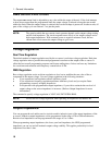
NOTE: To minimize the possibility of instability on the output, keep load leads as short as
possible bundle or twist the leads tightly together to minimize inductance
Current Ratings
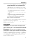
Fire Hazard To satisfy safety requirements, load wires must be large enough not to overheat
when carrying the maximum short-circuit current of the ac source. If there is more
than one load, then any pair of load wires must be capable of safely carrying the
full-rated current of the ac source.
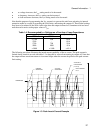
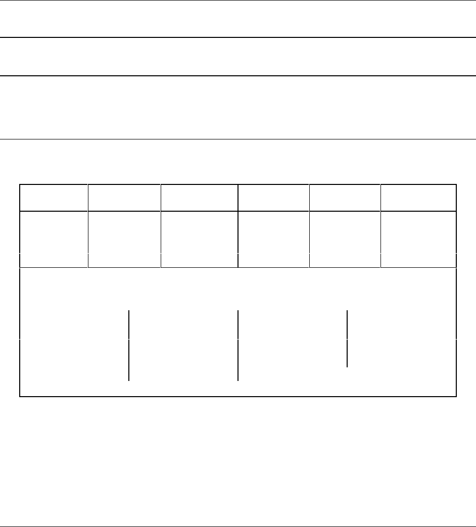
Table 2-1 lists the characteristics of AWG (American Wire Gage) copper wire.
Table 2-1. Ampacity and Resistance of Stranded Copper Conductors
AWG No. Ampacity
1
Resistance
2
(Ω/m)
AWG No. Ampacity
1
Resistance
2
(Ω/m)
14 25 0.0103 6 80 0.0016
12 30 0.0065 4 105 0.0010
10 40 0.0041 2 140 0.00064
8 60 0.0025 1/0 195 0.00040
NOTES:
1. Ampacity is based on 30
°
C ambient temperature with conductor rated at 60
°
C. For ambient
temperature other than 30
°
C, multiply the above ampacities by the following constants:
Temp. (
°
C)
Constant
Temp. (
°
C) Temp. (
°
C)
21-25 1.08 41-45 0.71
26-30 1.00 46-50 0.58
31-35 0.91 51-55 0.41
36-40 0.82
2. Resistance is nominal at 75
°
C wire temperature.
Voltage Drops
The load wires must also be large enough to avoid excessive voltage drops due to the impedance of the
wires. In general, if the wires are heavy enough to carry the maximum short circuit current without
overheating, excessive voltage drops will not be a problem. Refer to Table 2-1 to calculate the voltage
drop for some commonly used AWG copper wire. If load regulation becomes a problem refer to the
section "Remote Sense Connections".
Remote Sense Connections
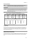
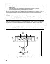
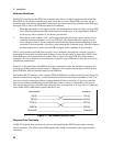
Under normal operation, the ac source senses the output voltage at the output terminals on the back of the
unit. External sense terminals are available on the back of the unit that allow the output voltages to be
sensed at the load, compensating for impedance losses in the load wiring. As shown in the following
figure:


