


1 - General Information
16
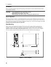
Peak Current/Dynamic Power Capability
The ac source can generate peak currents that exceed the rms current capability of the unit. This not only
applies when operating in ac mode, but also when programming output pulses in dc mode. Although the
unit will generate peak output currents up to 40A (
Agilent 6811B/6812B) or 80A (Agilent 6813B), the unit
can only maintain this output for a limited time. If the output of the unit exceeds the limit of the safe
operating area (SOA), the unit will activate its internal protection mode and turn its output off. This SOA
limit is based on output voltage, output current, output duration, and heatsink temperature.
NOTE: Refer to Chapter 4 on how to clear the unit when the internal protection mode has been
activated.
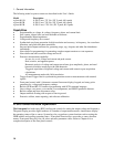
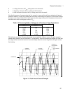
Peak Current Limit
By programming the peak current limit, you can prevent the unit from exceeding the safe operating area,
activating its internal protection mode, and turning the output off. The peak current limit circuit limits the
instantaneous output current. It functions by reducing the instantaneous output voltage to keep the output
peak current within the programmed limit. Because the circuit acts instantly, the effect is that it will clip
the peaks of the output voltage waveform. Additionally, with fast and/or large voltage transitions, the
unit may momentarily go into CC operating mode due to current in the output capacitor. This serves to
limit the rate of change of output voltage.
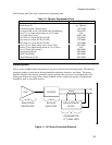
The following table gives approximate indications of how long the unit will tolerate peak output currents
before the SOA limits are exceeded. Because these values are voltage dependent, the table includes
various equivalent dc voltages along with the peak current values. The voltages shown in the table are
NOT the programmed voltages, but the average voltage values that will appear at the output when the
indicated high current condition exists. The SOA circuit becomes active at higher voltage and current
values as well as at longer duration times.
Table 1-3. Typical Peak Current Output Capacities
Agilent Agilent 6811B equivalent dc voltage when current is flowing
1
6813B Agilent 6812B 25 75 125 190 250 360
20 A 10 A >100 ms >100 ms >100 ms >100 ms >100 ms >100 ms
30 A 15 A >100 ms 100 ms 30 ms 24 ms 19 ms 15 ms
40 A 20 A 12 ms 9.2 ms 8.4 ms 7.6 ms 6.8 ms 5.9 ms
50 A 25 A 5.6 ms 5.1 ms 4.7 ms 4.4 ms 4 ms 3.5 ms
60 A 30 A 3.7 ms 3.4 ms 3.1 ms 2.9 ms 2.6 ms 2.3 ms
70 A 35 A 2.6 ms 2.4 ms 2.2 ms 2.1 ms 1.9 ms 1.7 ms
80 A 40 A 2 ms 1.8 ms 1.7 ms 1.6 ms 1.4 ms 1.3 ms
1
Based on 25C ambient temperature, with heatsink temperature less than 50C.
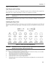
Peak Inrush Example
The following table gives the recommended initial I
peak
settings when the ac source output is a 127 Vac or
254 Vac 60 Hz sine wave, as a function of load capacitance. The load on the output is a full-wave bridge
along with the indicated capacitor. The load resistance across the capacitor is infinite. The recommended
I
peak
will change as a function of changes in input as follows: