


Front Panel Operation - 4
53
Action Display
1.
Press Voltage to access the Voltage Menu. Then press ô to access the voltage mode
command.
VOLT:M FIXED
2. On the Entry keypad, press ¯ or ° to scroll through the mode parameters to obtain LIST
and press Enter.
VOLT:M LIST
3.
Access the List Menu by pressing Shift List. The first menu command is the count. From
the Entry keypad, change the list count from the default (1) to 2. Press Enter.
COUNT 2
4. Access the List menu again and press ô until you access the dwell time. This specifies
the "on" time for each voltage point, which is effectively the output pulse width. The first
dwell point (0) appears in the display. On the Entry keypad, press . 0 3 3 and Enter.
DWEL 0 .033
5. Pressing the Enter key automatically advances to the step in the list. Enter the following
values for dwell list points 1 through 5: .067, .083, .067, .150, .067. Press Enter to
enter each value. When you finish, you will be at point 6, which is the end of the list.
Note: Press Shift Index or Shift ôIndex to access and edit any list point.
DWEL 1 .067
DWEL 2 .083
DWEL 3 .067
DWEL 4 .150
DWEL 5 .067
DWEL 6 EOL
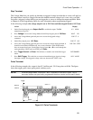
6. Press ô until you access the voltage list. This specifies the amplitude of each output point
during its corresponding dwell period. The first voltage list point (0) appears in the
display. On the Entry keypad, press 1 6 0 and Enter.
VOLT 0 160
7. Pressing the Enter key automatically advances to the step in the list. Enter the following
values for voltage list points 1 through 5: 0, 120, 0, 80, 0. Press Enter to enter each
value. When you finish, you will be at point 6, which is the end of the list.
Note: Press Shift Index or Shift ôIndex to access and edit any list point.
VOLT 1 0
VOLT 2 120
VOLT 3 0
VOLT 4 80
VOLT 5 0
VOLT 6 EOL
8. Press ô until you access the step command. Check that it is at the default mode (AUTO).
This lets a single trigger run your list for the specified count.
STEP AUTO
9.
Press Output On/Off to enable the output. The Dis annunciator will go off.
0 V 60 Hz
10.
Press Trigger Control and Enter to initiate the transient trigger sequence.
INIT:IMMED
11.
Press Shift Trigger. This sends the ac source an immediate trigger to generate the four
output pulses. The output returns to the immediate value at the end of the list.
Note: To clear a list, press Clear Entry. This truncates or clears the list at the presently
displayed list point. Each list must be accessed and cleared separately.
0 V 60 Hz
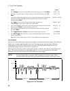
7 - Trigger Delays and Phase Synchronization
The ac source trigger system also lets you program trigger delays as well as synchronize output changes
to a specific phase angle of the output waveform.
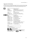
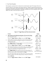
In example j, the output transient is triggered immediately at the receipt of the trigger signal. In example
ô, a delay time of approximately 16.7 milliseconds elapses between the occurence of the trigger and the
start of the output transient. In example í, the trigger source is programmed for phase synchronization,
which means that the transient occurs at the first occurrence of the specified phase angle after the trigger
signal is received.