


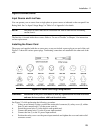

2 - Installation
26
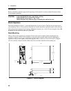
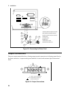
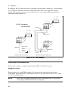
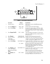
♦ Connect the phase 1 (1) sense terminals to the side of the load that connects to the corresponding
output terminal.
♦ Connect the Neutral (COM) sense terminal connector to the neutral side of the load.
♦ Twist and shield all signal wires to and from the sense connectors.
The sense leads are part of the ac source’s feedback path and must be kept at a low resistance in order to
maintain optimal performance. Connect the sense leads carefully so that they do not become open-
circuited.
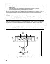
CAUTION: If the sense leads are left unconnected or become open during operation, the ac source
will regulate at the output terminals, but with a 40% increase in output voltage over the
programmed limit. The meter circuit cannot read back this increase in output voltage
when the sense lead is disconnected.
Set the ALC command to EXT (external) to enable remote sensing. The ALC command is located under
the Voltage key as explained in Chapter 4. Set the ALC command to INT (internal) to disable remote
sensing.
NOTE: If you are using external relays to connect and disconnect the load and sense
connections, do NOT permit the sense connections to open when remote sensing is
enabled. First disable remote sensing, then open the sense and load connections.
Figure 2-5. Remote Sense Connections
01
01
COM COM
SENSE
!
LOAD