


164-122012 Power
POD
400 Page 28 of 42
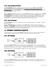
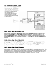
10.9. SERIAL COMMUNICATION
Follow the instructions in the section, WIRING THE POWER
POD
-400 for cabling and proper pin out for
serial communication with the unit. After insuring that the POWER
POD
-400 is wired properly, the unit
must be set up following the instructions in the section entitled, External Communications Setup.
The instruction set for the POWER
POD
-400 can be divided into two different types. They differ only in
that they
1. Write a command only or
2. Write a command and read a response.
Taking liberty with this vernacular, they may be differentiated using the terms COMMAND or QUERY.
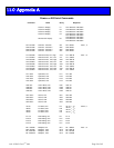
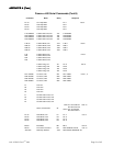
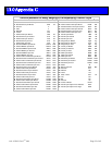
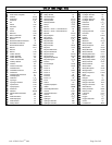
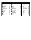
The entire set of instructions can be found in Appendix B.
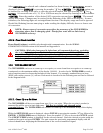
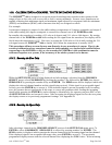
10.9.1. Commands
Typical RS-232 command structure is as follows: CMNDn<value>Cr
For example: To change channel three’s high alarm value to 75.00, send A3H075.00Cr.
RS-485 commands require only that an asterisk and the unit’s address precede the RS-232 Command.
Using the same example as above with a unit whose address is 10 (default), send *10A3H075.00Cr.
When the POWER
POD
-400 is the terminating unit on a 485 bus, two jumpers, CJ1 and CJ2 can be
shorted to add the required terminating resistors. Remove two machine screws from the rear of the top
cover. Slide the cover off. The two jumpers are near the serial communication connectors.
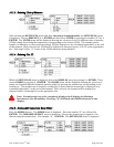
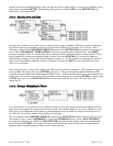
10.9.2. Set Point Queries
Queries are used when information from the unit is required. Each query is followed by a response from
the POWERPOD-400.
In this case, the query is asking for a programmed value. Specifically, the set point of channel three, which
happens to be set at 50.00 of 100.00.
Sent SP3Cr
Response SP3 050.00
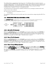
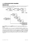
10.9.3. Alarm/Flag Queries
The state of the high and low flow alarms for each channel can be monitored via the DB-15 connecter (J8)
on the rear panel for immediate action from an alarm situation but the Totalizer set points can only be
monitored by reading a memory location’s Boolean setting via serial communication.
As shown in the section, Setting Limit Alarms, to simply QUERY channel three’s high alarm set point,
send A3HCr. Expect a response similar to A3H 075.00. The actual state of the alarm can be polled using
the STATUS query.
STCr
Which results in a response similar to
STATUS
OCA : CH1 AUTO CH2 CLOSED CH3 OPEN CH4 AUTO
HI/LO: 0/0 0/1 1/0 0/0
OCA is short for OPEN/CLOSED/AUTO.
HI/LO stands for the high flow limit alarm or the low flow limit alarm. One must parse the states if digital
tests are to be conducted.