


164-122012 Power
POD
400 Page 16 of 42
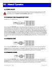
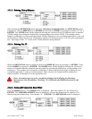
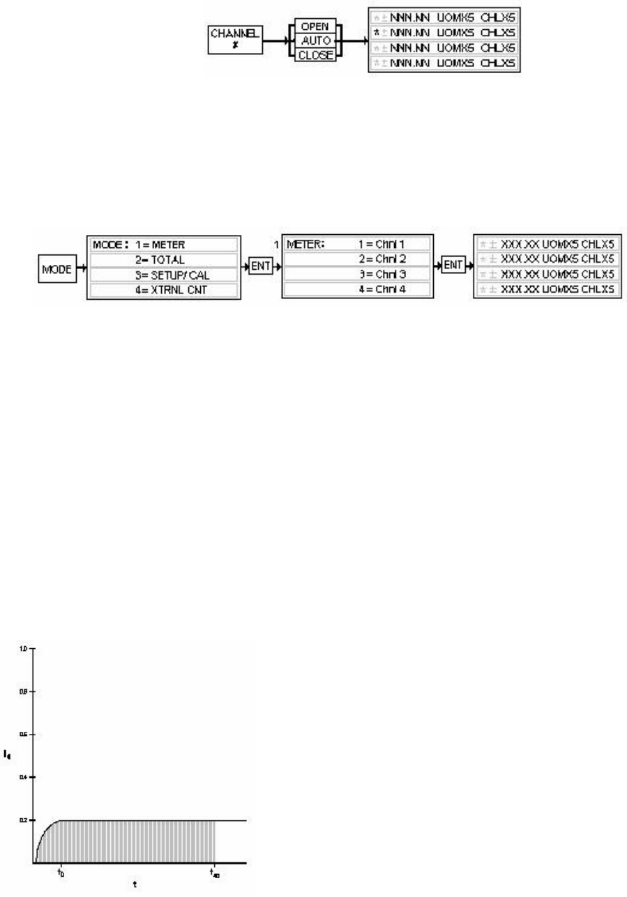
8.5. SETTING A CHANNEL TO AUTO CONTROL
Press the desired CHANNEL # key. An asterisk appears in the first space on the line representing the
selected channel. The meter display is immediately replaced with the current set point. Pressing the
AUTO key causes pin number eight (8) of the 15 pin Sub-D connector to float and returns the previously
programmed metering function to the display. Pin 14 signal levels are now available for control.
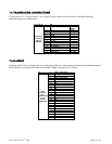
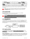
8.6. SETTING A CHANNEL TO DIRECTLY METER INCOMING SIGNALS
Press the MODE key. The MODE menu appears in the display. To select METER, press 1, and then
ENTER. The METER menu allows the selection of the desired channel. Press the number key that
corresponds with the desired channel followed by ENTER. The previously programmed display returns
with the selected channel reading the signal between pins 5 and 6 of the corresponding channel’s 15 pin
D-connector (J1 – J4).
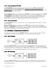
8.7. SETTING A CHANNEL TO DISPLAY THE TOTALIZER FUNCTION
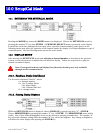
The POWERPOD-400 provides an integrated (Riemann Sum) value of the incoming signal for each
channel.
)**(
IS
fCfT
∑
= , where:
⎪
⎪
⎭
⎪
⎪
⎬
⎫
⎪
⎪
⎩
⎪
⎪
⎨
⎧
=
=
=
=
IntervalTimeFractionalf
ValueSpanorvalueCALC
FactorSignalFractionalf
TotalT
I
S
Each channel samples the incoming signal at a rate
corresponding to the preset A/D conversion rate in Hz. At
each sampling interval, the TOTALIZER function multiplies
the average signal, as a fraction of the full-scale value (5v, 10v
or 20 mA), times the span, or cal, value. This results in a rate
for that interval. Next, a time element factor is determined
according to the flow rate programmed for that channel as
follows.
For a time element of seconds, the factor is 1/10.
For minutes, the factor is 1/600.
Hours use a factor of 1/36000.
Each calculation is summed and stored for a TOTAL value.