


164-122012 Power
POD
400 Page 10 of 42
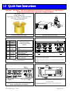
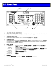
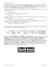
1. CHANNEL NUMBER SELECT KEYS
Selects channel for editing. An asterisk
(
*) appears in the first column
of the display
to indicate that this is the channel to
be edited.
2. OVERRIDE INDICATORS
Indicates when a channel’s command signal is overridden high
(
OPEN) or low
(
CLOSED).
3. OVERRIDE KEYS
Override the command signal on the
A
CTIVE CHANNEL.
OPEN
sets
control override (pin 8)
to +15V.
CLOSED
sets command to –15V. AUTO allows the user to set the command signal for normal operation. A channel must be
active before these keys can become operational.
4. DISPLAY AREA
Column 1: Reserved for displaying
A
CTIVE CHANNEL
(
*),
MASTER
channel
(
M),
SLAVE
(
S) or
TOTAL (T).
Column 2: Reserved for
p
olarity
indicator.
Col’s 3 – 8: Signal monitor. Displays current input signal while in
METER
mode,
A
VERAGE
while set
to average readings or TOTAL while in TOTALIZER mode.
Column 9: Spac
e
Col’s 10 – 14: UNITS OF MEASURE
display.
Column 15: Spac
e
Col’s 16 – 20: GAS
ID.
5. KEYPAD
Use to enter
SET POINTS
or to modify the
SETUP
or
CALIBRATION
of control unit.
5.0 Front Panel
CLOSE
P
Pod
ower
HASTINGS
OPEN
OPEN
CLOSE
OPEN
CLOSE
OPEN
CLOSE
1
4
3
2
7
1
4
0
9
3
6
8
2
5
.
400