


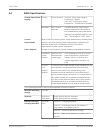
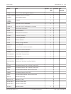


B520 Specifications
Voltage Input (Power
Supply)
Primary: 18 VAC terminal 18.0 VAC, 50 VA class 2 plug-in
transformer -TR1850
(18.0 VAC, 50 VA class 2 plug-in
transformer – TR1850-CA for Canada)
Secondary: Batt 1, Batt 2
terminals
The B520 Auxiliary Power Supply
Module supports the connection of
two independantly monitored sealed
lead-acid rechargeable batteries (12.0
VDC, 7 Ah through 12.0 VDC, 36 Ah).
Current
Requirements
Refer to the B520 Auxiliary Power Supply Module Battery Standby Chart
section in the B520 Auxiliary Power Supply Module Installation and
Operation Guide (P/B: F01U265445) for the current draw
requirements of other system components.
Power Outputs* All external connections are power-limited except battery terminals
Continuous
Power
Outputs
SDI2 Out, AUX
PWR terminals
(rated range)
2.0 A maximum at 11.5 to 12.2 VDC
(special application) (continuous
supply) total for all devices and
outputs supplied at Terminals 1-4,
6-36.
Fire and
Fire/
Burglary
Systems
To comply with UL 985 and 864 listing standards for fire
alarm systems, the total combined continuous and
alarm current draw for the system during alarm
conditions must be limited to 2.0 A provided by the
primary power supply (rectified AC). If current draw for
the system exceeds 2.0 A, remove connected devices
until the current draw falls below 2.0 A. Then connect
the removed devices to an additional B520 Auxiliary
Power Supply Module or to an external power supply
*For UL 864 applications, refer to the Compatible Accessories section.
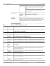
Minimum Operating
Voltage
10.2 VDC
SDI2 Bus SDI2 Bus A:
SDI2 Bus B:
8 VDC-2000 ft (610 m) maximum
8 VDC-2000 ft (610 m) maximum
Battery Discharge/
Recharge Schedule
Discharge
Cycle
13.2 VDC – Charging float level.
12.0 VDC – Low Battery and AC Fail Reports if
programmed. Low Battery LED on.
10.2 VDC – Minimum operational voltage.
9.8 VDC – Battery load (operation continue if AC is
present).
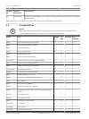
5.1
Control Panel Specifications | en 29
Bosch Security Systens, Inc. UL Installation Instructions 2012.12 | 02 | F.01U.265.462