


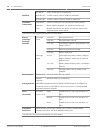

– Terminal 8: Output C (Switched Auxiliary Power)
PTC CB5 protects Terminal 24: Zonex Power.
PTC CB1 protects Terminal 32: SDI Power +.
PTC CB3 protects Terminal 36: SDI2 Power +.
Required by UL:
– All devices powered from a power output are to be supervised.
– Power outputs are not shared between fire and non-fire devices unless all devices are in
conduit within 20 ft, and in the same room.
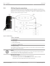
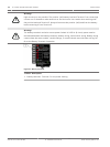
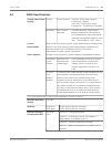
Power Outputs - Total Available Power
The system produces up to 1.4 A of combined power at 12.0 VDC Nominal for all powered
devices. The outputs listed below share the available power. These outputs are shown as red
circles on the faceplate.
– Terminal 3 - Auxiliary Power. Use this terminal to power devices requiring continuous
power.
– Terminal 6 (Output A) - Alarm Power Output. Programmable relay normally open, power
on alarm.
– Terminal 7 (Output B) - Alternate Alarm Power Output. Programmable relay normally
open, power on alarm.
– Terminal 8 (Output C) - Switched Auxiliary Power. Programmable relay normally closed,
switches power off when the Sensor Reset command is executed.
– Terminal 24 - Zonex Power. Use this terminal to power Zonex modules such as the
D8125, D8128D, and D8129 Modules.
– Terminal 32 - SDI Power +. Use this terminal to power serial device interface (SDI)
devices such as keypads, the D9210C Wiegand Control Interface Module, the ICP-
SDI-9114 module, and other compatible SDI devices.
– Terminal 36 - SDI2 Power +. Use this terminal to power serial device interface 2 (SDI2)
devices such as B208, B308, B426, B810, B920, B930, and other compatible SDI2
devices.
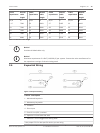
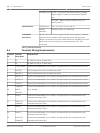
Power Outputs - Continuous Power Output Terminals 3, 8, 24,
32, and 36
The continuous current draw for powered devices connected to Terminals 3, 8, 24, 32, and 36,
and the accessory connector must not exceed 1.4 A. Devices powered from these outputs
must operate at 12.0 VDC Nominal.
Power Restricted for Fire and Combined Fire and Burglary Systems
Use the Fire System Power Formula to calculate the current available for fire and combined
fire and burglary systems (refer to Power Outputs - Programmable Power Output Terminals 6, 7,
and 8, page 24).
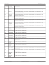
Power Outputs - Programmable Power Output Terminals 6, 7,
and 8
Programming
The power outputs at Terminals 6, 7, and 8 are programmed as Outputs A, B, and C. All
outputs are programmed in the Outputs section. Outputs are assigned a output type, (Fire
Bell, for example) when they are assigned to an area. Outputs can be assigned to one or more
areas. The Bosch defaults set Output A (Terminal 6) as a Steady Alarm Bell output, Output B
(Terminal 7) as a Pulsed Fire Bell output, and Output C (Terminal 8) as a Verification or Reset
output for smoke detectors. The D9412GV4/D7412GV4 v2.00 Program Entry Guide (P/N:
4.4
4.5
4.6
4.6.1
24 en | Power Supply and Power Outputs Control Panel
2012.12 | 02 | F.01U.265.462 UL Installation Instructions Bosch Security Systens, Inc.