


i
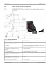
Notice!
For UL Certified accounts, additional power can be obtained using only a UL Listed auxiliary
12.0 VDC regulated, power-limited power supply.
i
Notice!
All terminals accept for Outputs A, B, and C (Terminals 6, 7 and 8) are supervised.
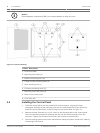
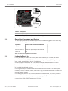
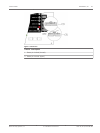
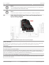
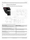
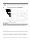
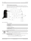
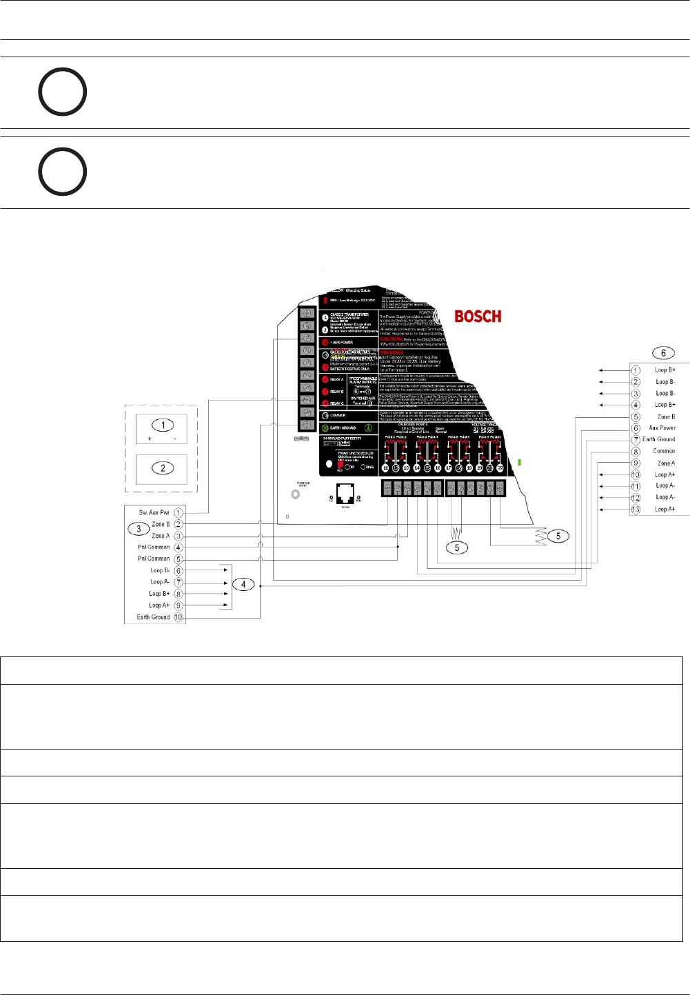
D9412GV4/D7412GV4 Input Points and Peripheral Devices
System Wiring Diagram
Figure 3.3: Input Points and Peripheral Devices System Wiring Diagram
Callout - Description
1 - (Optional): For 24 V applications use a UL 1481 Listed regulated, power-limited 24 VDC power supply with a
D130 Relay Module. Refer to the D130 Installation Instructions (P/N: F01U072455) for correct wiring
requirements.
2 - D130 Relay Module
3 - D125B Powered Loop Interface Module
4 - To UL Listed two-wire smoke detectors with a fire rated EOL resistor. Refer to Two-Wire Smoke Detectors
section in the Approved Applications chapter in the D9412GV4/D7412GV4 v2.00 Installation and System Reference
Guide (P/N: F01U265457) for a listing of compatible two-wire smoke detectors.
5 - 1 kΩ EOL resistor (P/N: F01U033966): For typical alarm applications.
6 - D129 Dual Class A Initiation Circuit Module: Provides optional Waterflow Alarm Retard feature. Not suitable
for two-wire smoke detectors.
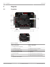
3.3
12 en | Diagrams Control Panel
2012.12 | 02 | F.01U.265.462 UL Installation Instructions Bosch Security Systens, Inc.