


i
Notice!
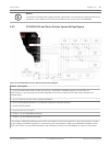
Terminals 24 through 36 are power limited, supervised. Fire and Intrusion devices must be on
separate circuits. Refer to ICP-SDI-9114 Installation Instructions (P/N: F01U030068)
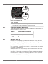
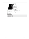
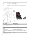
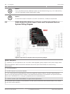
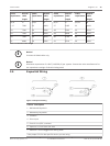
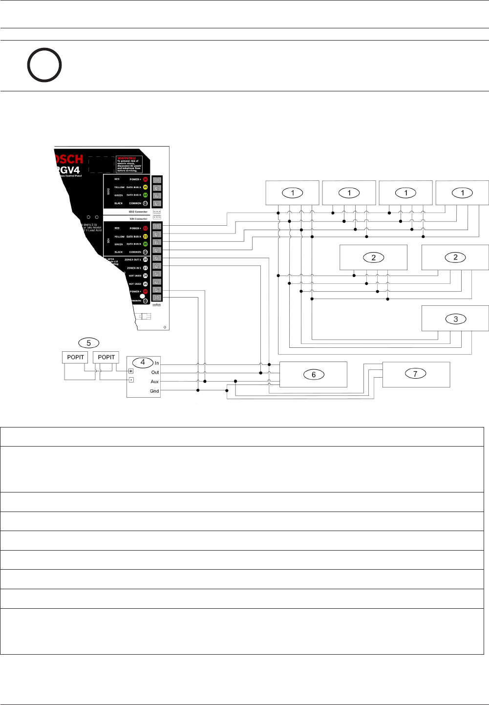
D7412GV4 SDI and Zonex Devices System Wiring Diagram
Figure 3.5: D7412GV4 SDI and Zonex Devices System Wiring Diagram
Callout - Description
1 - Up to 16 supervised D1265, D1255 (all versions), D1255RB, D1256RB Keypads, or D1257RB Fire
Annunciators, or up to 8 supervised D1260 Keypads (all versions) (maximum 16 supervised, maximum 32
unsupervised)
2 - Up to 2 D9210C Access Control Interface Modules
3 - Up to 2 B426/B420/DX4020 or ITS-DX4020-G Network Interface Modules
4 - D8125 POPEX Module
5 - Up to 67 D9127U/T POPITs
6 - Zonex 1: Up to 9 D8128Ds maximum
7 - Zonex 1: Up to 8 D8129s maximum
1
1
The number of D8129 OctoRelays that can be connected to each Zonex terminal on the control panel is limited
by the number of D8128D OctoPOPITs connected to the same terminal. Refer to the D8128D Installation Guide
(P/N: F01U070537) or the D8129 Operation and Installation Guide (P/N: F01U036302) for specific information.
3.4.2
Control Panel Diagrams | en 15
Bosch Security Systens, Inc. UL Installation Instructions 2012.12 | 02 | F.01U.265.462