


Chapter 1 – ACRCOMM – 3 –
ACRCOMM Overview
The ACRCOMM Plug-In Module provides serial communication ports (2
serial, 1 parallel) capability for the ACR1505 motherboard. ACRCOMM
external power input and User-SRAM battery back-up functions are not used
with the ACR1505 motherboard. These circuits are not populated on the
ACR1505 COMM Board.
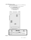
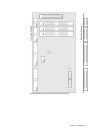
This section contains diagrams of the jumpers and switches on the
ACRCOMM module.
Serial Communications
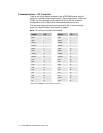
The ACR1505 serial communication interface is software configurable. At
power-up, the default COM1/COM2 communications mode is RS-232. For
ACR1505 boards with the communications option, the serial ports can be
configured by a serial port, or at power-up (or any time) via the PCI bus
communications port.
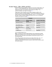
Table 1 and Table 2 show the configuration schemes for the ACR1505 board
with the serial communication ACRCOMM module option.
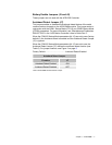
Factory Default........................................RS-232
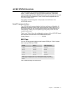
MUX Flags
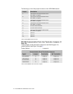
You can set the communications mode for each COM port. Table 1 shows
how to set up COM1and COM2.
MUX0 MUX1 COM Function
CLR (0) CLR (0) Not Used
SET (1) CLR (0) RS-232
CLR (0) SET (1) RS-422
SET (1) SET (1) Not Used
Note: For bit and flag numbers, see “COM1 Stream Flags” and “COM2
Stream Flags” in “Appendix B” of the “ACR Motion Controller User’s Guide,
Part 2.”
Table 1 COM1: MUX Flags and COM Functions