


– 18 – ACRCOMM and ACREXPAXIS User’s Guide
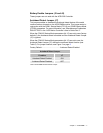
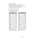
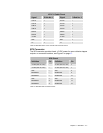
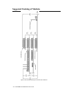
Module Encoder Pull-ups (Optional)
The ACR1505 can supply +5 VDC or +12 VDC pull-up resistors to each
encoder. Use Table 14 to determine the correct jumper configurations. For
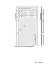
jumper locations, see Figure 3 on page 11.
Factory Default........................................Configured for +5 VDC for standard
Parker encoders
Encoder Pull-Up Jumpers
Encoder Resistor Jumper +5 VDC +12 VDC
10 RP1 JP1 Pins 1 & 2 Pins 2 & 3
11 RP2 JP2 Pins 1 & 2 Pins 2 & 3
12 RP3 JP3 Pins 1 & 2 Pins 2 & 3
13 RP4 JP4 Pins 1 & 2 Pins 2 & 3
14 RP6 JP6 Pins 1 & 2 Pins 2 & 3
15 RP7 JP7 Pins 1 & 2 Pins 2 & 3
16 RP8 JP8 Pins 1 & 2 Pins 2 & 3
17 RP9 JP9 Pins 1 & 2 Pins 2 & 3
18 RP5 JP5 Pins 1 & 2 Pins 2 & 3
19 RP10 JP10 Pins 1 & 2 Pins 2 & 3
Table 14 EXPAXIS Module Encoder Pull-Up Jumpers
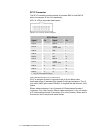
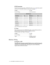
Module Software
To access axes 9 through 16, refer to the software manual for the
commands. In addition, AcroView Version 3.11 and higher can display the
extra parameters, and show and program axes 9 through 16.