


– 12 – ACRCOMM and ACREXPAXIS User’s Guide
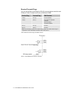
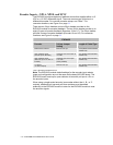
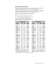
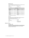
Encoder Inputs—XP1A, XP1B, and XP1C
The EXPAXIS module accepts any feedback device that supplies either a +5
VDC or +12 VDC differential signal. The most common type of device is a
differential encoder. For common encoder setups, see Table 7. For
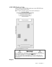
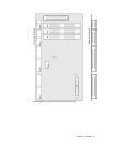
connector locations, see Figure 3 on page 11.
There are two 34 pin headers and one 20 pin header provided on the
EXPAXIS module for encoder feedback. The two 34 pin header provide up to
eight (8) axes of encoder feedback (Encoders 10 thru 17). The 20 pin header
provides 2 axes of encoder feedback (Encoder 18 and 19). For connector
locations, see Figure 3 on page 11.
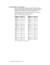
EXPAXIS
Encoder Pull-up Jumper
Setting
Length of Cable/Type
Differential Line Driver Remove Pull-ups 100 ft.(Beldon 9330 Shielded
Twisted Pair)
Open Collector Driver
(No Pull-ups on Encoder)
Install Pull-ups and Jumper to
+12 VDC
75 ft. (Beldon 9330 Shielded
Twisted Pair)
Open Collector Driver
(With Pull-ups to +5 VDC on
Encoder)
Install Pull-ups and Jumper
to +5 VDC
(factory Default)
50 ft. (Beldon 9330 Shielded
Twisted Pair)
TTL Driver
(+5 VDC Outputs)
Remove Pull-ups 50 ft. (Beldon 9330 Shielded
Twisted Pair)
Table 7 EPXAXIS Feedback devices
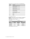
Note: The EXPAXIS module default settings for the encoder input resistor
types and configuration are not the same as the base ACR1505 board. The
EXPAXIS board is set-up for open-collector drivers with pull-ups to +5V on
the encoder inputs.
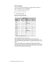
When using a single-ended encoder (an encoder without the A-, B-, or Z-
outputs), additional pull-ups and pull-down resistors must be added
externally to the EXPAXIS module in order for the EXPAXIS module to read
the encoder signals.