


9
SMARTBOX Installation
SMARTBOX™ Controller for HONEYWELL™ Wind Turbine WT6500 Owner’s Manual - Rev14
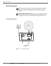
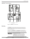
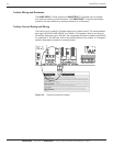
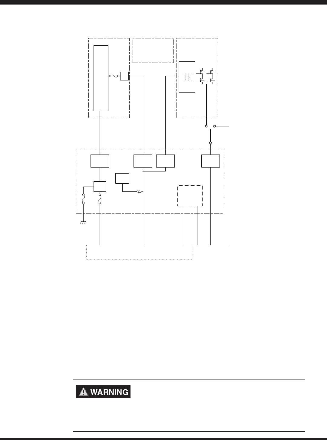
SMARTBOX™ Controller Diagram
DC
GFI
WIND TURBINE
HV POWER
INPUT
CHARGE
CONTOL
CURRENT/
VOLTAGE
SENSING
CURRENT/
VOLTAGE
SENSING
CURRENT/
VOLTAGE
SENSING
CURRENT/
VOLTAGE
SENSING
OVP
AC
TRANSFER
SWITCH
SYSTEM
POWER
ISOLATED
LOGIC
CONTROL
24V
BATTERY
BANK
TURBINE
LOGIC
CONTROL
RS485
AC OUT AC GRID
EQUIPMENT
GROUND
IO BOARD
CHARGER INVERTERDSP CONTROL
FROM TURBINE
Figure 2.2 SMARTBOX™ Controller Diagram
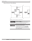
Mounting
The SMARTBOX™ Controller must be mounted vertically and installed indoors in a
dry,protectedlocationawayfromammablematerial,sourcesofhightemperature,
moisture and vibration. The location must also be sheltered from direct sunlight, rain,
snow and wind-blown debris.
It is best to mount the SMARTBOX™ Controller near near the building’s electrical
panel egress. This will typically result in the SMARTBOX™ Controller being mounted
on or near an external wall where the battery enclosure can then be located outdoors.
RISK OF FIRE OR EXPLOSION
Toreducetheriskofreorexplosion,donotinstall
the SMARTBOX™ Controller in sealed compartments
containgin batteries or in locations that require ignition-
protected equipment. Failure to follow this warning may
result in death, personal injury or property damage.