


12 8494/95/96G/H Operating And Service Manual
Operating Instructions
Operating Instructions
CAUTION Do not apply RF power greater than 1 W average, or 100 W peak with a
maximum pulse width of 10 microseconds. If these limits are exceeded, the
attenuators may be damaged.
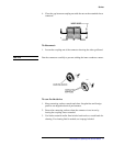
CAUTION Do not ground both solenoid drive pins at the same time. This causes rapid
cycling of the solenoid and could reduce the operating life of the attenuator.
The rapid cycling may produce a buzzing sound from the attenuator.
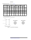
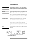
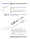
Either RF connector may be used as the input or output connector. Connect
the solenoid drive cable to the solenoid drive connector (J1). By applying the
proper voltage and grounds to the proper pins of J1, the attenuator will either
increase or decrease the amount of attenuation as selected.
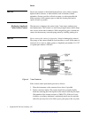
Operator’s Check The Operator's Check is supplied to allow the operator to make a quick
check of the instrument prior to use or if a failure is suspected.
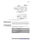
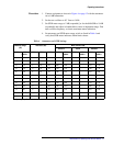
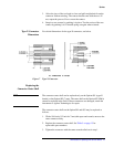
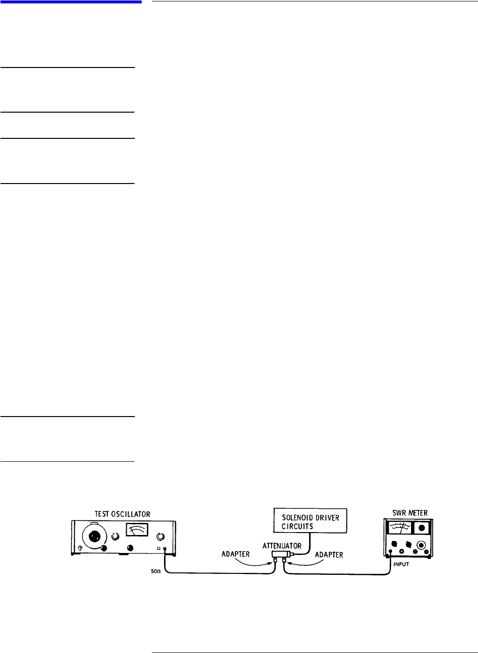
Description The attenuator is driven from a 50-ohm signal source at 1 kHz. The output
level from the attenuator is detected by a narrow-bandwidth voltmeter. The
attenuator and detector range switches are stepped together and the
variations in level noted. This verifies that each attenuator section is being
properly switched and checks the low-frequency accuracy of the attenuator.
NOTE The SWR meter used in this check is calibrated for a square-law detector and
therefore the range changes and errors (read in dB) are twice that indicated
by the meter.
Figure 4 Operator’s Check Setup