


2 8494/95/96G/H Operating And Service Manual
Overview
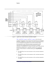
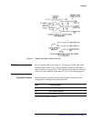
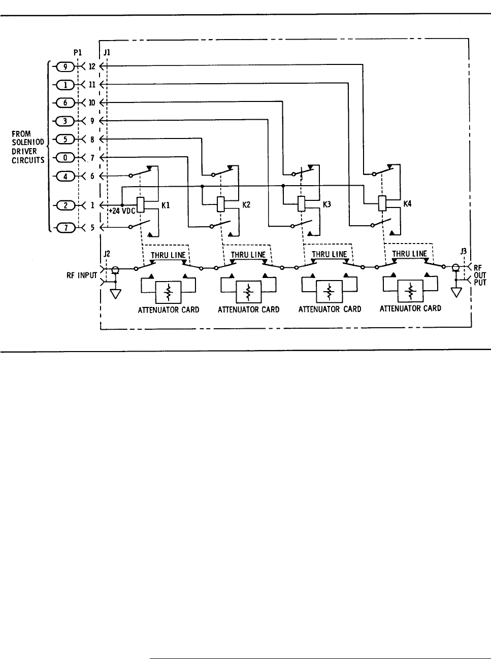
Figure 1 Typical Four Section Attenuator Schematic Diagram
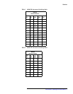
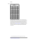
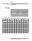
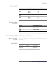
Table 1 and Table 2 on page 3 and Table 3 on page 4 show the typical
switching arrangement to increase the amount of attenuation in an 8494G/H,
8495G/H, or 8496G/H in a linear manner. To ensure specified performance,
it is recommended that the attenuator sections that are shown in the
following tables be used. With the attenuator programmed for 0 dB
attenuation, the resultant attenuation is the insertion loss (residual
attenuation). The 8494G/H has a minimum selectable step of 1 dB, while the
8495G/H and 8496G/H have a minimum selectable step of 10 dB. The
accuracy of the attenuators is within the limits given in Specifications,
page 6.
• The 8494G/H are four-section attenuators with a maximum attenuation
of 11 dB.
• The 8495G/H are three-section attenuators with a maximum attenuation
of 70 dB.
• The 8496G/H are four-section attenuators with a maximum attenuation
of 110 dB.
NOTE
Solenoid (K4) and
associated circuitry
are not available in
models 8495G and
8495H.