


Page 90
5.3 Single Phase Speed Counter
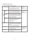
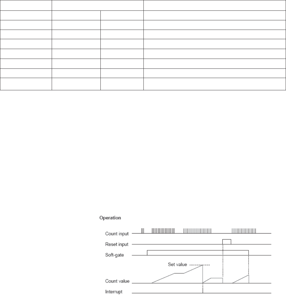
When the count input is changed from OFF to ON, the count value is increased by 1. When the count value reaches
the set value, the count value is reset to 0, and I/O interrupt program is activated (if the interrupt enable flag is ON).
The count value is reset to 0 when the reset input comes ON. This counter operation is enabled while the soft-gate is
ON. The count value is reset to 0 when the soft-gate is changed from ON to OFF. The set value is set internally at
the timing of the soft-gate changing from OFF to ON. When the soft-gate is OFF, count value can be changed by
writing the data into the set value register and setting the count preset flag to ON. The count value range is H0000
0000 to HFFFF FFFF (32-bit data).
Hardware Condition:
Count input (IP 1 and IP 2) (X000 and X001)
ON/OFF pulse width: 10 micro or more (max. 50 kHz)
Reset input (X002 and X003)
ON/OFF duration: 2 ms or more
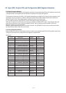
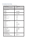
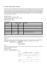
Related Registers:
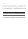
Function Register/device Remarks
Channel 1 Channel 2
Count input IP 1 (X000) IP 2 (X001)
Reset input IP 3 (X002) IP 4 (X003)
Set value MW12 SW13 MW14 MW15 Data range: H0000 0000 to HFFFF FFFF
Count value MW16 MW17 MW18 MW19
Soft-gate M320 M328 Operation is enabled when ON
Interrupt enable M322 M330 Interrupt is enabled when ON
Count preset M323 M331 Used to preset the counter value
Note1:
When both the channels are configured in high speed mode, IP1 to IP4 cannot be used as normal input devices.
However, if either one channel is configured in high speed mode, the inputs for other channel can be used as normal
input devices.
Note2:
Two words are used for storing the double word (32bit) count/set values. Lower word will contain Lower 16bit value
and Higher word will contain higher 16 bit. This register storage scheme is applicable for all the modes.
value. Eg. Count value : MW16,MW17
So if count value is (Hex) 87654321
MW16 = 4321 (Hex)
MW17= 8765 (Hex)
Note3:
Input 3 and input 4 are used as reset inputs for count inputs 1 and 2. So do not use input 3 and 4 as normal inputs
when PLC is configured in this mode.
Interrupt assignment
Channel 1 --- I/O interrupt program #1
Channel 2 --- I/O interrupt program #2