


Page 46
R
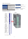
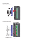
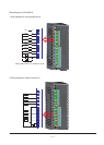
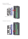
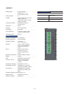
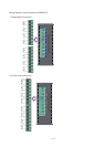
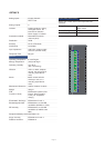
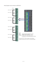
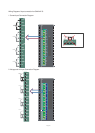
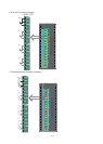
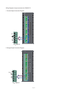
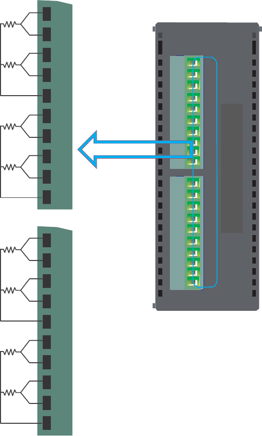
Wiring Diagram of input connection for GRT208**S:
RTD
PT1000
Input Channel 0
Input Channel 1
CS1
AIN1
CS2
AIN2
PWR
CS1
AIN1
AGND
CS2
AIN2
Input Channel 2
Input Channel 3
Input Channel 4
Input Channel 5
Input Channel 6
Input Channel 7
CS3
AIN3
CS4
AIN4
AGND
CS5
AIN5
CS6
AIN6
AGND
CS7
AIN7
CS8
AIN8
AGND
AGND
CS3
F
AIN3
L
CS4
AIN4
A
AGND
0
CS5
8
AIN5
0
CS6
0
AIN6
AGND
CS7
AIN7
CS8
AIN8
AGND
Note:
CSx:
Current source(x equals to 1 to 8)
AINx: Analog input(x equals to 1 to 8)
AGND: Analog ground.Analog ground for
all channels is internally shorted on PCB
Connect RTD PT100 as shown in the above
diagram between the points CS, AIN and AGND