


Page 118
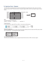
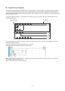
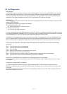
8.1.1 Power Supply Check
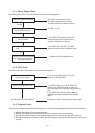
If the PWR (power) LED is not lit after power on, check the following points.
Check the power connection Connection terminals are correct.
The terminal screws are not loose.
The terminal block is installed securely.
Correct
Check the power voltage 24 VDC; +/- 15%
at the V200’s terminal
Normal
Remove the programmer If the PWR LED becomes normal, the
port connector internal supply may be shorted in the
external connections of this port.
Still unlit
Remove the expansion If the PWR LED is still OFF, the V200
Unit basic unit may be faulty. Replace the unit.
Lit
Insert the removed expansion Replace the faulty expansion unit.
Unit one by one to pinpoint
the faulty expansion
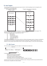
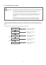
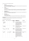
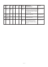
8.1.2 CPU Check
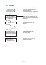
If the RUN LED is not lit after power on, check the following points.
Check the position of the If it is not in R (RUN) position, turn the
mode control switch switch to R (RUN) position.
Check the ERR (error) LED If the ERR LED is lit, the V200 CPU PLC
model is in the ERROR mode. Confirm the
error message by connecting the programming
tool.
If only ERR LED is blinking either ladder or
application is invalid. Download the program
again.
Is the RUN & ERR LED blinking ? Firmware is invalid. Download the firmware again.
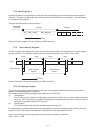
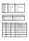
8.1.3 Program Check
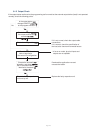
Check the user program based on the following points if it is running but the operation does not work as intended.
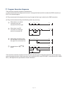
1. Whether duplicated coils are not programmed.
2. Whether a coil device and a destination of a function instruction are not overlapping.
3. Whether the ON/OFF duration of an external input signal is not shorter than the unit’s scan time.
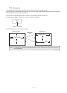
4. Whether a register/device which is used in the main program is not operated erroneously in the interrupt
program.