


–
8
–
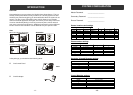
After mounting the door sensor, it - Please ensure the magnet is aligned with
doesn’t work anymore. the red marking on the transmitter.
- If you are mounting the sensor on to a
metal door or window, a spacer may be
required to avoid magnetic interference
caused by the metal door / window.
- Make sure the sensor is within the operation
range of the control panel by bringing it
closer to the control panel.
My motion sensor is not very The motion sensor is designed to detect the
responsive, sometimes when I walk “First Motion”. First Motion means no motion
by it, the control panel doesn’t respond, is detected within the past 20 seconds,
but sometimes it does. and if a motion is then detected, that is the
“First Motion”. So if you continue to walk
in front of the motion sensor, it will only
pick up the first motion. Unless you wait
for 20 seconds, then walk again, the control
panel will respond. Otherwise, the control
will only respond to the first motion.
TROUBLE SHOOTING
–
45
–
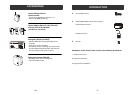
When a sensor is triggered, the - Make sure the battery in the sensor is
control panel doesn’t respond at all, installed properly, pay attention to the
what is the problem? polarity.
- Make sure the sensor is learned to the
control panel. Follow instructions on
page 34 on how to learn a sensor.
- You may try to bring the sensor closer to
the control panel, ensure it is not out of
the operation range.
My motion sensor sometimes gets Ensure the motion sensor is not facing
triggered by itself, how can I prevent direct sunlight, nor any A/C or furnace
that? vents. You may also reduce the sensitivity
to low. If your motion sensor is located
outdoors, you may want to relocate it.
Sensors
INSTALLATION
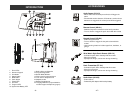
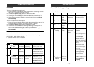
5. After inserting the rechargeable battery, the LO
BATT LED will be off if the battery is fully
charged, otherwise it will be on.
6. Connect the phone line from the wall socket to
the “LINE” socket inside the battery
compartment.
7. [OPTIONAL] If another telephone that will be
using the same telephone jack, you may
connect this telephone to “PHONE” outlet of
the control panel by a phone cord (not
provided).
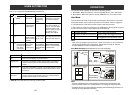
8. The phone line(s), cord of the power adapter
should all come out from the lower right corner of
the control panel in order to close the battery
cover properly.
9. The battery cover can now be closed, and tighten
the 2 screws to secure the battery cover.
PWR, ARM, PROG LEDs should be flashing,
zone LEDs should be off.
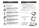
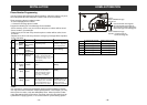
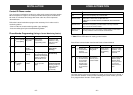
4. Insert the rechargeable battery to the battery compartment. There are 2
different types of rechargeable battery for 2 markets:
a. North American Version: Lead Acid
Connect the 2 wires to the battery. Red wire
connects to the “+” terminal on the battery.
Black wire connects to the “-” terminal on the
battery. Markings on the battery should face up.
b. European Version: Ni-MH
Plug in the wire from the battery to the battery
socket inside the battery compartment.
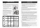
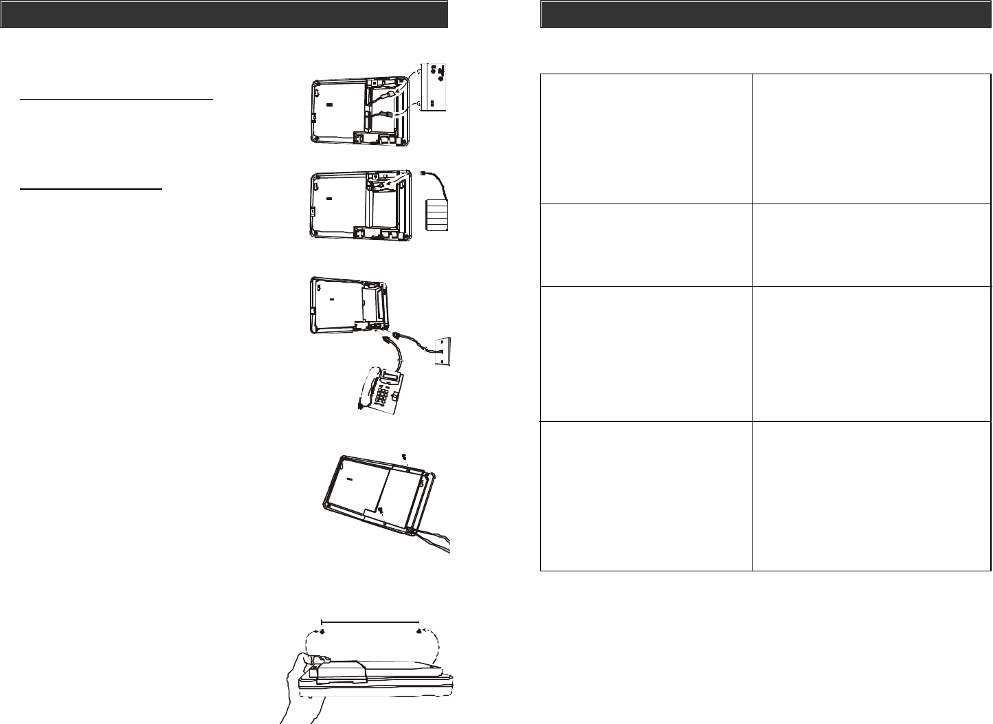
7-1/8"
10. The control panel is intended to be mounted on a
flat wall. 2 screws are required to mount the control
panel securely on the wall. It should not be mounted
too high or too low. In most situations, just below
eye level is ideal.
11. Once you have selected the mounting location,
tighten 2 screws on the wall. They should be
7-1/8" apart from each other, on the same
horizontal level. Do not tighten the screws
all the way in, leave about 1/8" from the
wall in order for the control panel to be
hanged onto the wall.
(Optional)